-
StatusCompleted
-
Status date2021-06-03
-
Activity Code5C.393
The objective of the project is to develop and qualify an assembly of multiple C to Q band converters intended for Very High Throughput Satellite communication payloads employing digital transparent processors for maximum traffic allocation flexibility. The equipment translates a C band output (3 GHz bandwidth) of the processor DACs to a Q band downlink frequency towards the gateways, with a compact and modular unit that must meet very challenging mass and cost targets.
The equipment will be conceived with the best possible compromise between conflicting requirements of compactness and modularity/flexibility, and with a wide operating bandwidth in order to be reused with minimal adaptations in multiple programs
Main challenges are:
- Wide operating band: 3 GHz in C & Q band with particular attention to
- Output Return Loss in coaxial output at Q band without isolator
- Very demanding filtering requirement in C band
- Wide-band sub-harmonic mixer
- To include 4 Q band RF chains in parallel in one unique hybrid module
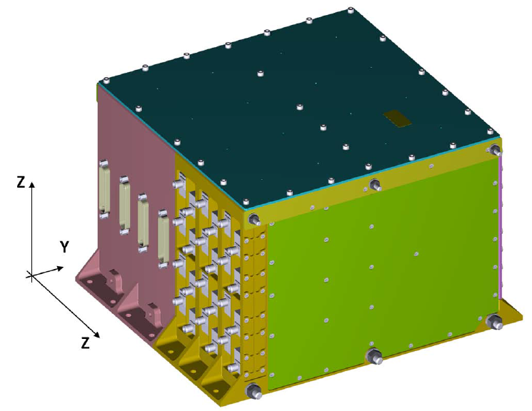
- Compactness of the unit: 252 x 195 x 150 mm
- Management of the reliability of the unit which includes several centralised functions for the 24 RF chains
This development is a key enabler of TAS’ offering of VHTS systems to address commercial and institutional demands for global high rate data connectivity at affordable prices, as a contribution to the solution of digital divide in Europe and worldwide.
Thanks to the wide operating bandwidth, it can be reused with minimal adaptations both in the programs guided by TAS, as part of an overall offer of satellite systems, and by other Primes, with TAS acting as supplier of subsystems and electronic equipment.
The product has the following features:
Electrical characteristics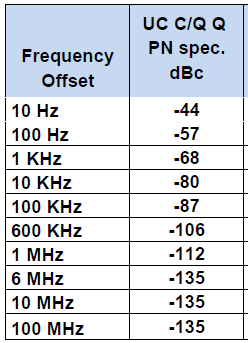 :
:
- Number of RF C/Q Up-Converter chains: up to 24
- Input frequency: 3.8 to 6.7 GHz
- Output frequency:37.5 to 40.4 GHz
- LO signal: 33.7 GHz
- Gain: 28 dB
- Noise Figure: 17 dB at ambient Temp.
- Phase Noise as per below table
Design features
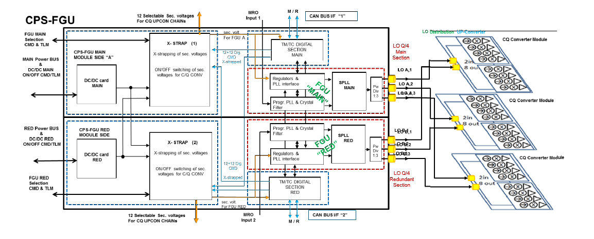
A. CPSFGU module
Each of the 2 modules is a double side module containing
- DC-DC Converter circuit,
- Cross Strapping board
- Digital TM/TC Board
- Frequency Generator circuits.
Design Concept
- The FGU section provides a LO/4 frequency in the 8.425 to 8.925 GHz range to the LO distribution card that splits the inputs to the Up converters.
- DC-DC converter provides all the biasing line required by the circuits and by means of the Cross-strapping card and
- TM/TC CAN interface the C/Q RF chain ON /OFF commands for the required payload configuration.
Critical Technologies:
- SPLL Hermetic hybrid circuit
- Fractional synthesis for the SPLL reference circuit
- Centralized High power supply circuits
- Digital microprocessor board for the TM/TC CAN interface.
B. RF UpConverter Modules
Design Concept:
Each chain of the UpConverter modules translates a 3.8 to 6.8 GHz IF
bandwidth to the Q band downlink band within 37.5 to 42.5 GHz.
Critical Technologies:
- RF hermetic hybrid multi-cavity module (4 RF chains in one module).
- Microstrip to coaxial 2.4 SMA hermetic transition in Q band over 3 GHz
The unit is an assembly which includes 24 RF C/Q UpConverter chains.
The unit is composed of two sections:
- CPSFGU section
- RF Upconverter section
CPSFGU section
This centralized section, which, at top level provides secondary voltages and LO signals to all the 24 RF up-converter chains is composed of two identical modules: main and redundant one
RF Up-converter section
This section is composed of three modules
Each of the three modules includes:
- One LO distribution circuit
- Two RF Up-converter hybrid modules with 4 RF chains inside each hybrid module
The block diagram and a drawing of the unit are reported in the below figures
The Project was carried out in two phases:
- Technological phase, in which a preliminary design of the unit was delivered and a production phase leading to the production of an engineering qualification model (EQM) of the unit. The first phase lasted 7 months and ended in August 2020 with the TRB of the engineering models of the main components of the unit;
- Production phase, lasted 9 months and ended with the TRB of the EQM and final review in May 2021.
Production, assembly, integration and testing of the EQM model of the CQ CONVERTER was completed.
The Project is currently being closed with the following activities:
- presentation of the EQM test report;
- Final Report.