
-
StatusCompleted
-
Status date2017-06-22
-
Activity Code4E.057
Key requirements are a selection of the requirements which have determined the design and development. These are the most important performance requirements which put a major constraint on the design as well as other requirements. The following table gives a summary of the key requirements. Note that the actual requirement text is more detailed than in this brief overview.
Key technical requirements/targets
| Requirement | Value/target | Remarks |
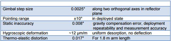
| Thermo-elastic distortion | <0.015° | To be achieved by minimizing thermal gradients (MLI, materials with high conductivity) and the application of low-CTE material. |
| Repeatability | <0.008° | Between successive deployments; |
| Stiffness | <0.015° @ 0.0075 m/s² | Depointing due to linear S/C accelerations |
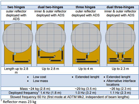
| Deployed frequency | >0.7 Hz | Target for 1.8 m arm length and a reflector mass of 30 kg. |
| Mass | <23kg | Target for 1.8 m arm length, to be minimized within constraints of stiffness and cost. |
| Integration accuracy | Alignment of hinges for successful stowage, alignment reproducibility of S/C and reflector interfaces |
Challenges for the project were:
- Leverage from ADSN experience of deployable structures.
- Make use of heritage of release mechanisms, and provide input to the design of the next generation of Hold Down Release System (HDRS), the NELS system
- Design a system that meets the stringent requirements of accuracy and stiffness , and demonstrate via test
- Make a system that consists of building blocks that can be assembled in various configurations, being able to offer a large degree of flexibility without the need for high non-recurring cost for each new configuration.
- Design and develop required tooling for assembly, alignment, test and deployment. Were possible make use of our experience gained during our Solar Array programs (light weight deployable structures). And design this tooling such that it supports the required system flexibility.
- Allows to fold up the extension arm, attach an antenna to a S/C during launch, release and extend the Antenna away from the S/C body when in orbit
- Provide a stable position for the antenna in both the stowed and the deployed configuration , while allowing to control the pointing of the antenna over a pre-defined range with great accuracy in the deployed position
- Flexibility to accommodate a variety of S/C and antenna configurations
The A-ADS has a modular design which allows a wide range of mission configurations by tuning only a few design parameters. . This approach in combination with the use of standard building blocks minimizes the non-recurring design effort for a specific application and allows any desired configuration. A special kinematic model is available to assess the design parameters of the A-ADS based on customer inputs (stowed and deployed reflector position & orientation and S/C interface location). These parameters are transferred to 3D-CAD for verification and to quickly establish the A-ADS design for the specified antenna configuration and accommodation. Some examples are given below:
Key parameters for ADS are:
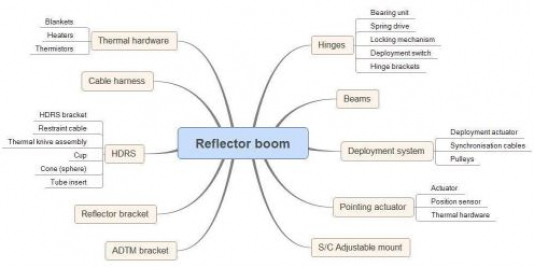
Assembly, Integration and Test features
- Reproducible mounting interfaces at S/C and reflector side
- Adjustability of ±5-7 mm / 2° in all directions at S/C interface, hold-down brackets and reflector interface
- Deployment testing by means of helium balloons
The A-ADS system has two main functions:
- Deploying the antenna reflector from the stowed position to its nominal operational position and orientation
- Pointing of the reflector during the S/C lifetime
The antenna configuration differs from mission to mission (different focal lengths, reflector diameters, stowed configuration). The A-ADS will be designed such that a wide range of mission configurations can be covered with a standard, configurable design. This is to minimize the non-recurring effort in a project.
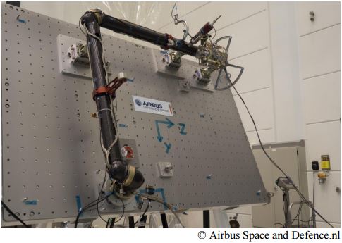
The EM design is shown in Figure 4.1. The shown configuration has an arm length of approximately 3meter.
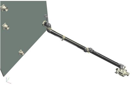
The A-ADS has spring driven hinges at the joints. All hinges have an opening angle of 180° except for the root hinge which has a customized opening angle depending on the configuration. When fully opened the hinges are locked and a stiff support structure for the reflector is obtained. At the end of the arm a gimbal is located which is able to point the reflector around two axes with a resolution of 0.0025°. The gimbal or pointing actuator is an off-the-shelf unit with flight heritage (ADTM Mk2 by Airbus DS UK). A synchronization system ensures a synchronous deployment of the hinges and the deployment speed is controlled by an actuator. The deployment actuator restrains the motorization springs and actually works as a break rather than as an actuator. Once deployed and latched, the ADTM Mk2 is used for trimming and continuous pointing of the reflector.
In summary the project covered the following steps:
- Requirements consolidation
- Complete the conceptual design
- Preliminary design of the individual items:
- Hinge
- Tubes
- Synchronisation mechanism + Cable
- Deployment actuators
- modification of the NELS Hold Down system to be used for the ADS
- Procurement of individual parts
- Procurement of the ADTM
- Test of the individual items: stiffness and repeatability tests
- Integration and alignment of the EM model and the related tooling and test set-up.
- EM Functional testing
- EM vibration test
- Repeat of Functional test (alignment and stiffness test)
- Analysis of results
- Test reporting
All activities in the ARTES 5.2 project are completed ready to progress to formal qualification under an ARTES 3-4 project.