-
StatusCompleted
-
Status date2023-01-23
-
Activity Code7C.048
The increased demand for bandwidth in airplane telecommunications, resulting from the need for new services for passengers such as in-flight Wi-Fi, traditionally carried out by Ka-band, has led to an interest in the use of higher frequencies. The activities planned to be done in the frame of Q-/V- band Aeronautical Antenna project concerns the design and analysis of a low profile dual polarization/dual band (Ka and Q/V) mobile terminal for Aeronautical applications, including a V-band Up-converter and a V-band High Power Amplifier (HPA).
Based on the defined specifications and the results of the design activities, the following demonstrator models will be manufactured and tested (TRL 4):
-
Q-/V- band three axes Satcom Antenna Demonstrator Model
-
V-band Up-Converter Demonstrator Model
-
V-Band High Power Amplifier Demonstrator Model
Furthermore, in the frame of the project, a possible solution will be identified for the radome operating in the Ka, Q, and V bands, selecting the material, performing simulation and tests (in the ESA facilities) using acquired samples.
The key challenges of the project can be summarized as follows:
-
Design and manufacturing of the antenna optics operating at Q-/V- band
-
Design and manufacturing of the RF chains components (i.e., Q-V-/band feed, Q-/V-band filters, Q-/V-band polarizer)
-
Design and manufacturing of the V-band up-converter considering the current state of art of the technology
-
Design and manufacturing of the V-band SSPA considering the current state of art of the technology
The proposed AMAS architecture for an Airborne Antenna operating at Ka, Q and V band provides the following benefits:
-
Allow the use for aeronautical user link of Q/V frequency bands in anticipation of the expected congestion of the Ka frequency band currently used for aeronautical services for passengers
-
Allow the use of an Airborne Antenna that can also use the Ka band as an alternative to the Q and V, facilitating the migration to these new bands, and ensuring the continuity of the service in areas not covered by satellites operating in the Q/V frequency bands.
-
the architectural choice based on multi reflector, that is on the integration of two transmission systems in a single antenna, allows to increase the continuity of the aeronautical service in case of a failure of one of the two systems.
This project represents the first step in a roadmap which aims at the development of a certified Q-/V- band mobile terminal to be used for aeronautical application.
The next steps will be used to bring the current state of the project (TRL 4) to a qualified terminal to be used for flight tests (TRL 5-6).
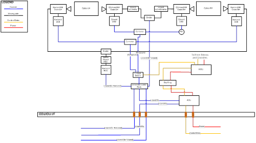
The AMAS is composed by the following main Sub-Systems:
-
Satellite antenna
-
Versatile Antenna Control Unit (V-ACU)
The Satellite Antenna subsystem includes the following main components:
-
Antenna optics (multi-reflector)
-
QV-Band RF chain (including Q-Band LNB)
-
Ka-Band RF chain (including Ka Band LNB)
-
RJSR: Integrated Rotary Joint-Slip Ring and mounting structure
-
PLT: Positioning System Platform including:
-
Azimuth Motor and Encoder
-
Elevation Motor and Encoder
-
Cross-Travel Motor and Encoder
-
QV-Band Polarization Switching Motor Motor and associated sensors
-
Ka-Band Polarization Switching Motor + associated sensors
-
Base plate + turning table including Motor Drive Units (MDU)
-
Mirror Switching Motor.
-
MDU: The Motor Driver Unit is the subsystem in charge of controlling the motor axis motion and reading the axis sensors information.
-
-
V-band and Ka-band SSPA and Up-Converter (UC)
-
RF Switch Unit.
A Rotary joint and a slip ring are required to interface static and rotating part of the system.
The project plan foresees the following reviews:
-
SRR (System Requirements Review) with the scope to review the requirements at system level and their apportionment to lower levels
-
PDR (Preliminary Design Review) with the scope to review the results of the preliminary design, and in particular to identify the most critical items to be manufactured and tested before their design freezes
-
CBTR (Critical Breadboard Test Review) with the scope to analyse the result of the tests performed on the manufactured critical items
-
DDR (Detailed Design Review) with the aim of freezing the design of all the items and giving the green light to the production of AMAS
-
FR (Final Review) with the aim of analysing the results of the performed test on the Demonstrator models and to verify the compliance with the defined requirements
Completed.