-
StatusCompleted
-
Status date2018-02-22
-
Activity Code4G.006
At system level, the main interest is to offer flexibility to the Operators in the following cases:
Satellite co-location
The evolution of the satellite fleets inside the same orbital position can lead to TCR frequency coordination difficulties. The implementation of TCR sub-systems with command frequency flexibility capability can ease the coordination process.
Satellites re-location
The change of orbital position can also lead to coordination difficulties for TCR frequencies. The possibility to change them is, in that case, a strong advantage.
Jammer avoidance
In case the current command frequencies are jammed, it is possible to select another command frequency far enough from the current ones in order to avoid any jamming.
The objective is to propose this frequency flexibility capability keeping roughly the same recurring price at unit level and to launch the related units with a TAS SPACEBUS platform.
The target of the development was to extend the frequency flexibility range to 750MHz in order to cover the whole RF Ku band 13.75GHz to 14.5GHz. .
The frequency step obtained is 100kHz, which covers all the operator step requirements.
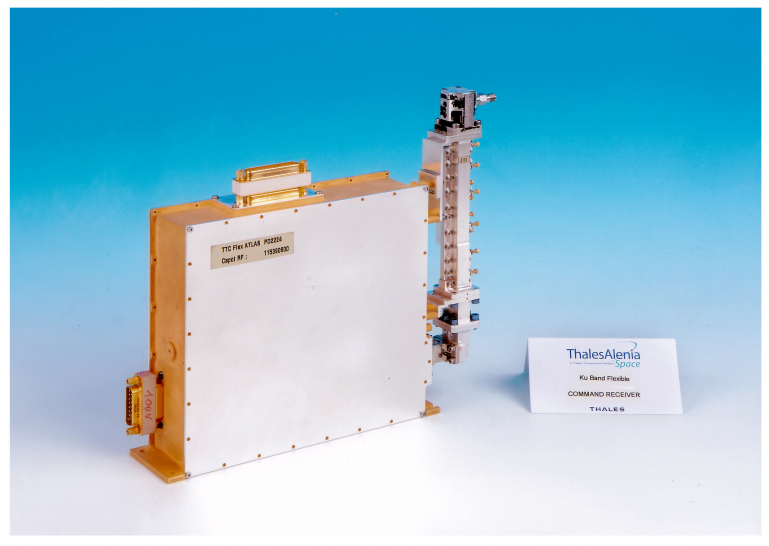
Because the wide band flexible local oscillator has been already developed in the ARTES 4 ESTEC CONTRACT N° 4000100602/10/NL/US, the challenge of the project was to design, to manufacture and to qualify the Interface board hosting the function able to command the frequency change inside the Command Receiver. This function has been developed inside an FPGA. In addition, an upgrade (AD829 FP) on the IF board was designed and routed.
The Qualification of this Interface board had to be compatible with the schedule needs of the final operator (EUTELSAT).
This SPACEBUS Flight Qualified FF TTC Rx allowed the success of following programs on other platform (with Interface board derived from SPACEBUS one) and recent flexible programs on TAS SPACEBUS.
The Frequency command management function inside the FPGA is summarized hereafter.
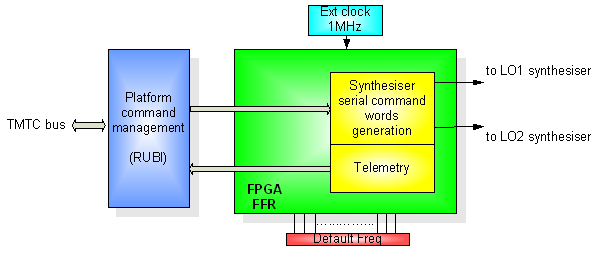
- FPGA clocked by 1MHz external clock achieved thanks a Schmitt trigger
- FPGA is linked to RUBI SPACEBUS INTERFACE via 16 bits serial link
- Synthesizer parameters linked to each RF frequency are stored in the FPGA
Start up frequency of the FF CMR is determined by straps wiring on the Interface Board
The development plan of the Interface Board, FPGA & IF/LO/Demo Board upgrade was:
- Definition of the command and telemetry protocol
- Architecture definition of the FPGA
- FPGA detailed design and VHDL coding
- Interface board detailed design
- IF/LO/Demo board upgrade (AD829 FP) with manufacturing at EQM level
- EM Interface board manufacturing
- EM Interface board with FPGA validation test with LO
- EQM built up by using some sub-assemblies from the FF TTC receiver EQM manufactured during the FF TTC Rx main development (ESA contract 4000100602/10/NL/US)
- PFM Manufacturing
- Qualification of EQM and PFM
The project is completed.
The SPACEBUS FF TTC receiver is in-orbit with nominal in-orbit performances after 2 years operating period. The FF CMR is the standard unit CMR for the TAS SB4000 platform and has been adapted for other platform (more than 10 units have been produced).