-
StatusCompleted
-
Status date2020-04-24
-
Activity Code5C.302
The main project objective was an improvement of input IP3 of at least 3 dB over the whole frequency band compared to state-of-the-art mixers used in down-converters. Mixer linearity also strongly depends on in-band harmonics (i.e. -1 x LO + RF for Ka-band mixer). Thus, a trade-off between linearity in terms of input IP3 and in-band harmonics needed to be found.
The main challenge was the design of a very highly linear mixer boosting the state-of-the art IP3 by 3 dB.
As system architecture a double balanced diode ring mixer was designed. The integrated GaN circuit design included all baluns and an LO drive amplifier. In addition, an LTCC package for the Ka-band mixer was designed. The Ka-band downconverter-mixer was assembled into the package and measured. Measurements were compared to simulations results. The design of the integrated circuit was performed using ADS and MOMENTUM). The design of the LTCC package was performed using IMST’s EMPIRE 3D FTDT simulator.
IMST also examined Gilbert cell structures. While these structures can provide the required input IP3 of +25 dBm, the dissipated power is 1.2 W. Therefore, Gilbert cell mixers in GaN are not suitable.
Cold-FET structures could not be analysed due to the lag of valid models.
After first design iteration all parts (baluns, amplifiers, passive elements) were in perfect agreement with the measurements. However, the diode model of OMMIC was NOT suitable for the design of diode mixers. The activation voltage of the diodes was much larger than the one of the models. This leads to huge required LO power (+30 dBm) in order to achieve +25 dBm input IP3 and affordable conversion loss.
The project was finalized in March 2020. Despite of the model inaccuracies (OMMIC), IMST showed a way forward using UMS GaN technology for this purpose.
In the frame of the project IMST designed two downconversion mixers. One mixer operated in Ka-band, the other mixer operated in Ku-band. Both mixers featured integrated baluns. In addition, IMST also designed two LO driver amplifiers in order to provide the required LO power to the mixer. The project aim was the design of mixers, which exceed the current state-of-the-art input IP3 by 2...3 dB. The ESA specification for input IP3 was set to +25 dBm.
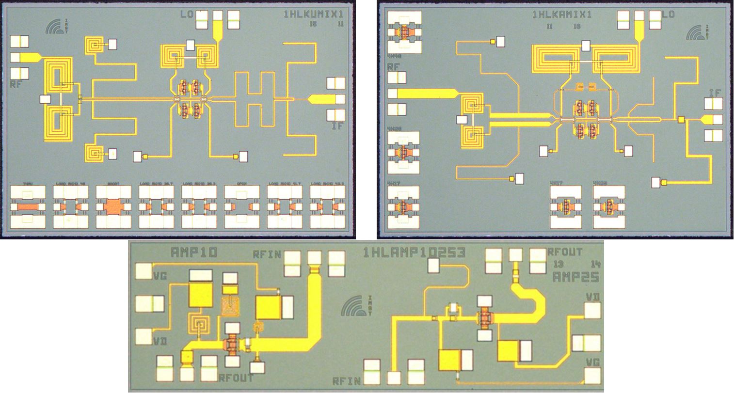
Figure 1: Chip Photograph of Ku-Mixer, Ka-Mixer and buffer amplifier test structures.
IMST chose OMMIC, France as GaN technology supplier a conducted the design work. When measuring the device it turned out that all passive designs (e.g. baluns) were in perfect agreement to the measurements. The same was true for the active devices. Both amplifiers were in perfect agreement to the measurement (Fig. 2).
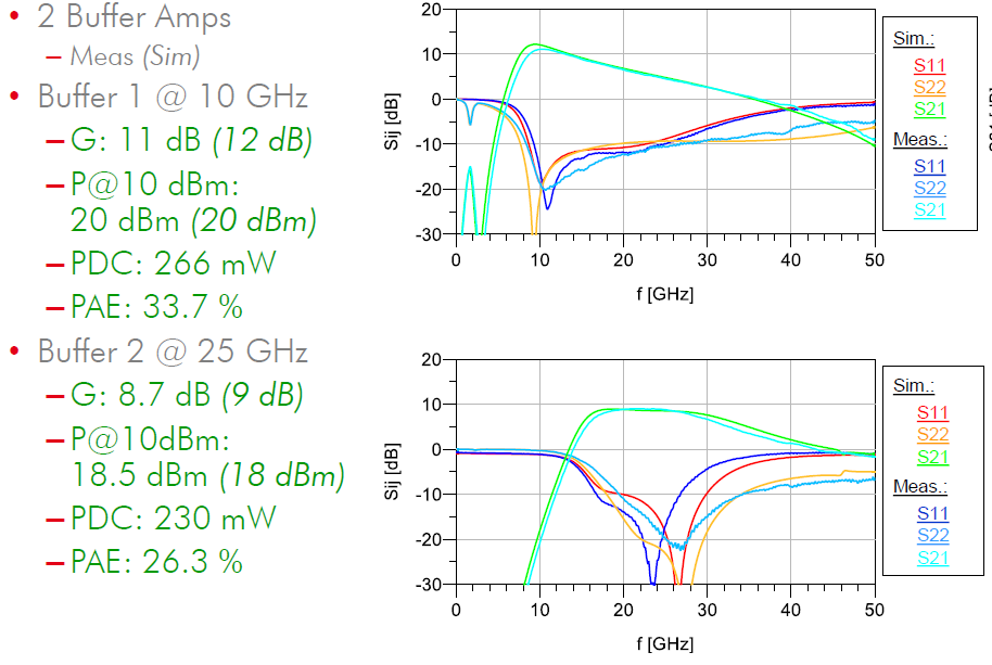
Figure 2: Comparison of measured and simulated results for both buffer amplifiers.
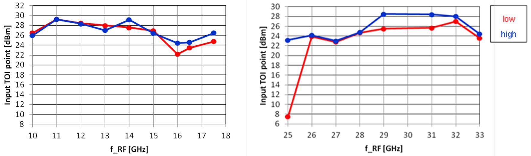
Figure 3: Left: Ku-band mixer input TOI. Right: Ka-band mixer input TOI
Figure 3 shows the measured input TOI of both mixers. Basically both mixers reached the goal of an IIP3 better than +25 dBm. However, both mixer devices showed a huge deviation from simulation (Fig. 4). While the principal mixer behavior was present, a much larger LO drive power was required in order to operate the mixer devices (+30 dBm instead of +16 dBm).
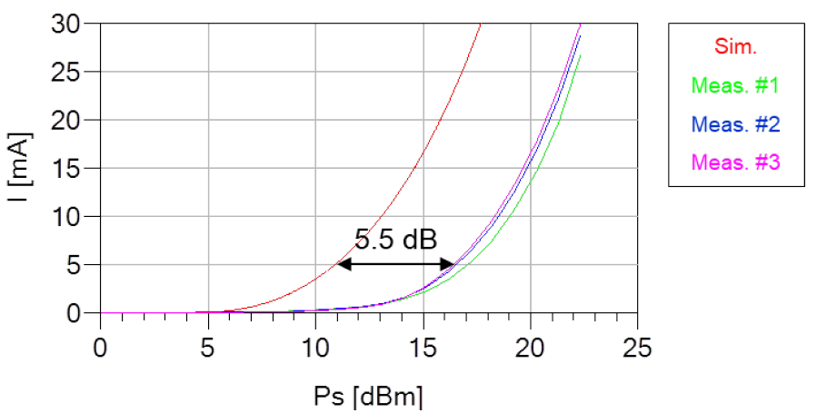
Figure 4: Comparison of simulated and measured activation power for a single GaN diode.
During examinations it turned out that the OMMIC diode model derived from a short-connected transistor delivered wrong simulation results, although OMMIC clearly stated in an e-mail that a short-connected transistor model can be used as a diode model and was reliable. Under these circumstances it does not make sense to use the OMMIC GaN technology for the design of passive diode ring mixers. In order to show a way out IMST examined UMS GaN technology. In doing so, UMS diodes (again short-connected transistors) were measured. Afterwards, measured values were compared to simulations. The UMS model matched the measurements very well.
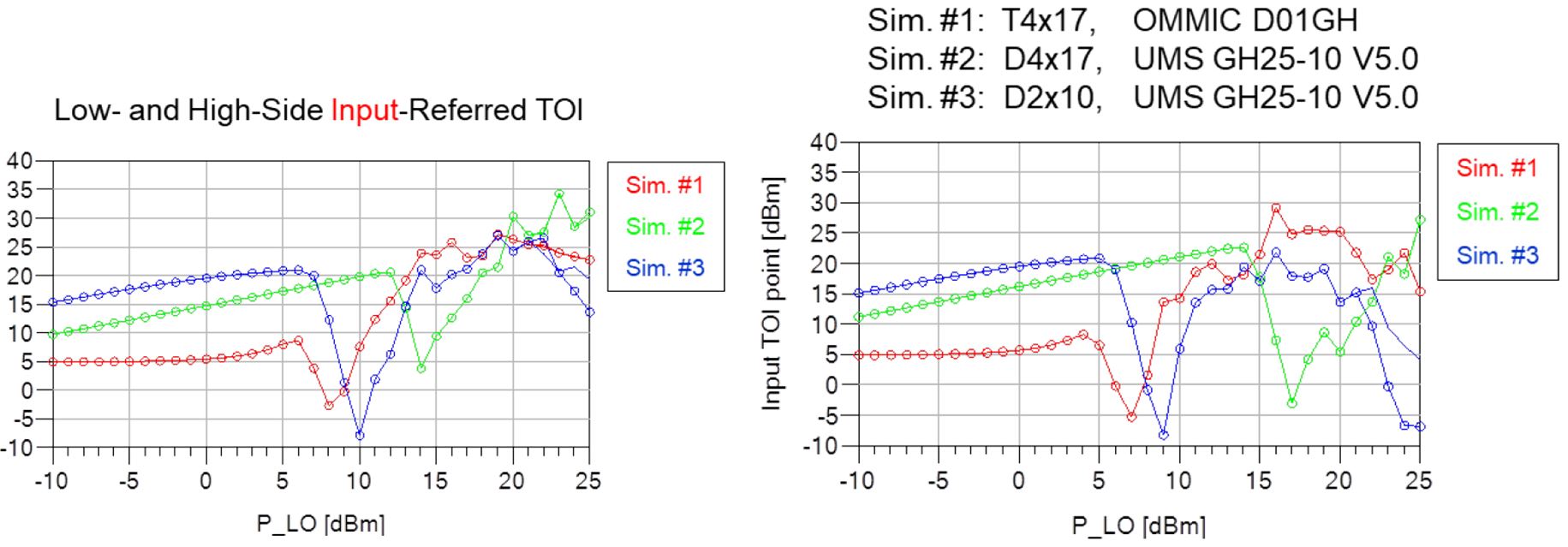
Figure 5: Left: Ka-band mixer IIP3 and right: Ku-band mixer IIP3. OMMIC (#1), UMS V1 (#2) and V2 (#3)
When placing the UMS models into the OMMIC mixer design also the pure mixer performance was in the expected range (Fig. 5). Basically the same performance could be achieved but just like for OMMIC at very high LO power levels. Therefore, IMST concludes that the UMS GaN technology can be used to design passive diode ring mixers. However, UMS GaN was limited at project start in maximum and transit frequency. This technology could be used for the design of a 10 GHz LO driver amplifier but not for the design of a 25 GHz LO driver amplifier. This situation may change in future due to new processes available at UMS with higher transit and maximum frequency.
Summary:
IMST clearly showed its design capabilities in the frame of this ESA project. All circuits were a first shot success. This is true for the passive circuits as demonstrated on the baluns. This is also true for the active circuits as demonstrated on the amplifiers. The OMMIC transistor model however cannot be used for diode simulation. It shows a diode activation voltage, which is at least 1 V lower than the real transistors used as diodes. Although OMMIC stated in a first email that the model was correct, it was not. Later OMMIC confirmed this issue. Unfortunately, due to this reason it does not make sense to design a passive ring diode mixer using OMMIC GaN technology.
Afterwards, IMST examined UMS GaN technology. Although this technology cannot be used in order to design active amplifiers in Ka-band (LO driver), the UMS GaN diodes show an expected behaviour and the UMS model fits very well the diode measurements. IMST proved in a principal design that a passive diode ring Ka-band down converter mixer designed in UMS GaN technology can fulfil the linearity requirements. But it is also to be stated that also here the LO-power drive levels are in the range of +20 dBm or higher. The Ku-band mixer simulation clearly shows that it is not possible to reach the linearity requirements.
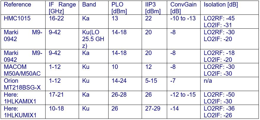
To enable a clear view on the results a state-of-the-art comparison of both Ka- and Ku-band mixers is given in the following table. The input IP3 is around 4 dB higher in Ka-band and more than 6 dB higher in Ku-band. It must be stated that only mixers are included in the comparison that are featuring the same IF band (not low frequencies DC-some GHz). Most mixers on the marked are having IF frequencies in the range of DC to some GHz. State-of-the-art Comparison