
-
StatusCompleted
-
Status date2014-12-02
-
Activity Code7A.014
With the rapid increase in demand for high data rate communications among mobile users, there is a considerable and increasing demand for systems operating at higher frequencies where bandwidth is more readily available to deliver the data rates needed. Antenna design is particularly challenging in Ka-band due to tolerance issues and increased losses and as a result there are very few competitors offering systems based on flat panel array technologies.
The objective of this programme is to demonstrate the application of novel antenna technology to enable the aperture size, in particular its height, to be reduced as far as possible whilst maintaining the required performance. The project has produced a demonstrator antenna to an advanced prototype standard which is sufficiently representative of production units to allow preliminary qualification of the design.
The ohmic losses in the antenna must be minimised in order to maintain gain and G/T whilst reducing the aperture height considerably compared with conventional reflector technology. In addition, the sidelobe templates are stringent in order to minimise interference to other satellites. The relatively high frequency means tight tolerances must be maintained in order to avoid degrading the performance of the antenna. The aperture should be common to receive (20 GHz) and transmit (30 GHz) bands to use all the limited space available for maximum performance, requiring a broadband antenna design.
Also key is the mechanical robustness and thermal stability of the antenna. The antenna includes relatively large, unsupported areas, which must not distort during the manufacturing process or during operational service under harsh shock and vibration conditions and wide temperature extremes.
There is a substantial emerging market for portable and SOTM Ka-band terminals worldwide and there are few non-US suppliers. Hence, there is a good commercial opportunity to develop a competitive product.
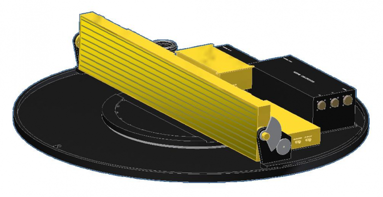
The height of the overall antenna system including baseplate, positioner and Radome is less than 300mm and has a footprint of about 950 mm whilst existing reflector systems are typically 600 – 900 mm tall, making the solution highly attractive for a wide range of applications ranging from satellite news gathering, security and emergency service applications through to military uses. The Hurricane system offers comparable performance to the taller antennas at a significantly reduced size. It is noted that the antenna aperture is designed to meet the full 2GHz transmit and receive bandwidths.
The HURRICANE Antenna System will consist of a rectangular array mounted on a low profile gimbal mechanism. The complete System will be an autonomous unit with its own internal tracking controller and attitude and heading reference unit (AHRS). It will interface to a satellite modem in the vehicle via an Antenna Cabin Control Unit (ACCU).
The interface to the Antenna System will consist of Tx and Rx IF channels, a DC power input and a control interface.
The Tx amplifier chain is mounted off-board, to allow flexibility to select different power levels for different applications without causing heat dissipation problems within the radome enclosure.
The antenna is assembled as the set of key subsystems Line Replaceable Units (LRUs). Built In test functionality will identify faults down at least to the LRU level and, in some cases, to individual components within a given LRU. Fault indication will be provided inside the vehicle via the ACCU, and also can be sent via an RS232 port in the ACCU to a laptop computer.
This project has focussed on the antenna aperture only, since this was the highest risk element of the technology. Cobham has de-risked the tracking system through completion of a parallel programme which is focused on an SHF tracked low profile antenna of similar dimensions, as well as undertaking it own privately funded investment. As a result of this programme Cobham is now well placed to enter the market with Ka-band array based solutions and to offer array antennas to systems integrators for various applications.
WP1000: Business Development
Detailed requirements definition and specification fine-tuning.
WP2000: Outline Antenna Design
Top-level antenna architecture design including performance predictions and mechanical layout.
WP3000: Assessment of Manufacturing Options
Evaluate options based on cost, tolerances, performance, environmental stability etc.
WP4000: Feed Chain and Azimuth Beamformer Design
Detailed design phase.
WP5000: Elevation BFN and Radiating Structure Design
Detailed design including elevation amplitude taper, power splitters, radiating aperture.
WP6000: Polariser Design
Detailed design phase.
WP7000: Mechanical Breadboard Design, Manufacture and Test
Preliminary mechanical stress and thermal analysis/test.
WP8000: Design, Manufacture and RF Test of Complete Ka-Band Antenna
Prototype antenna manufacture/test.
WP9000: Project Management
The project is complete: the antenna has been designed, constructed and successfully tested.