

-
StatusCompleted
-
Status date2015-11-13
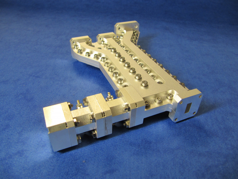
The Photograph shows the fully assembled, and tuned, silver plated Ka-band quadruplexer. Working from left to right across the photograph, the first channel is the tunable Rx1 channel. The initial block is the TE101 mode input resonant cavity which feeds into a pair of tunable dual mode cavities which are then bolted to the main clam shell body (which also contains aTE101 cavity). The next feature at the back of the photograph is the common port. Working towards the front of the photograph the square block in the centre of the quadruplexer is the housing of Tx2’s rectangular dual mode cavity. The first of the three flanges is the Tx2 port, next to this is the Rx2 port and finally Tx1.
The objective of this activity is the design and manufacture of a quadruplexer which operates over the extremes of a waveguide band. Such a quadruplexer enables a single feed to be used for transmit and receive functions at Ka-band frequencies. Without the quadruplexer a long waveguide run operating close to cut-off at the transmit frequencies would present an unacceptably high loss between the feed and the payload. There would also be a high risk of PIMP interfering with the receive channels.
With these basic objectives in mind, the activity focuses on reducing losses within the channel filters whilst simultaneously addressing wide rejection bandwidth which ultimately allows simpler payload filtering.
The range of bandwidths, centre frequencies and rejection requirements requires unique realisations for optimal performance of each channel. The high power aspects of the two transmit channels requires special attention whilst the receive channels may utilise more appropriate techniques for low power, low loss filters. To control unwanted effects over such a wide band requires detailed attention to the manifold design.
The main challenges of this programme are multiplexing over a wide operating area and as such wide pass bands. Channel and junction interactions have to considered and controlled to prevent degradation of in-band performance and rejection. The manufacturing tolerances required may also prove to be challenging.
One of the main benefits of the quadruplexer is to allow a single feed rather than a multi-feed antenna. In the worst case a standard solution may require two antennas. By incorporating the quadruplexer with the other feed components, loss in the waveguide run between the payload and the feed can be reduced significantly, particularly at transmit frequencies.
Design skills, methods and knowledge gained from the project can also be applied more generally to produce better products with less demanding multiplexing requirements such as diplexers and triplexers.
Each channel filter is realised using technology to achieve the lowest loss given the rejection requirements.
SYSTEM ARCHITECTURE
The quadruplexer consists of four channel filters each with a unique waveguide realisation. The filters are multiplexed via a waveguide manifold which includes elements to control resonance effects.
The first stage of the project is a trade-off different realisations and topologies for the various filters and manifold. Following a successful DTR the project progresses to detailed design and analysis before a manufacturing readiness review. Once manufactured the project proceeds to the tune and test stage before writing of the final report.
The project is complete. Design, manufacture, tune and test has been completed and reported. The final report has been issued