
-
StatusCompleted
-
Status date2021-07-09
-
Activity Code4E.071
The first phase of the development of the NELS hold down and release system covered the definition of requirements, technology investigation, and breadboard testing and concept design. As a result, a trade-off was made between the concept designs and decisions were made for the concept used for the Engineering Model.
In this next phase of the project, Airbus DS NL qualified the design.
For testing the “test as you fly” principle was adopted, which means Airbus DS NL followed the same sequence of steps as would be seen during an actual system integration, launch and activation in space flow.
The main challenges that had to be resolved arose when using elements from the NELS EM design and from EM GSE to build up flight representative items and test equipment to meet requirements under qualification level test conditions. To ensure proper functioning under these entire worst-case environmental test conditions, Airbus DS NL had to augment the EM test equipment, change the design and supply of the Heater Plates, and had to make small but important modifications to the parts of the mechanical design of NELS. Airbus DS NL was able to separate the structural (mechanical) elements of the test from the functional (cutting) elements, therewith performing the qualification in two separate parts. That allowed keeping the planning manageable.
During execution of the test campaign, Airbus DS NL found that the control release voltage range had to be limited to 20V due to limitations of the heater plate design. As it turned out this coincided with the release of the ECSS standard that specifies the same value. This finding was supported by information from Space Craft designers, which confirmed there is no immediate future need for higher control voltages than 20V.
Another factor was that a possible additional application of the NELS mechanism (for hold down and release of Antenna Booms) is no longer pursued by Airbus DS NL, as competitors for this equipment tend to use their own release mechanisms. Hence, the qualification for the NELS configuration variant to support that application - though started - was halted, although there is still a proposal running for such an application.
Looking at the test flow (see below figure) the confidence tests were done to confirm that the newly designed and procured heater plates were able to cut under all conditions.
Throughout the qualification campaign we made use of 3 QM grade NELS configurations, a low- and a high NELS stack intended to qualify the design for the envelope of Solar Array applications (2 to 5 panels), and a stack that was intended for Antenna Boom application. Over time we exchanged parts that needed to be modified, used all 3 NELS configurations and repeated tests if representativeness of previous test configurations was questioned.
Below figure depicts the executed test flow.
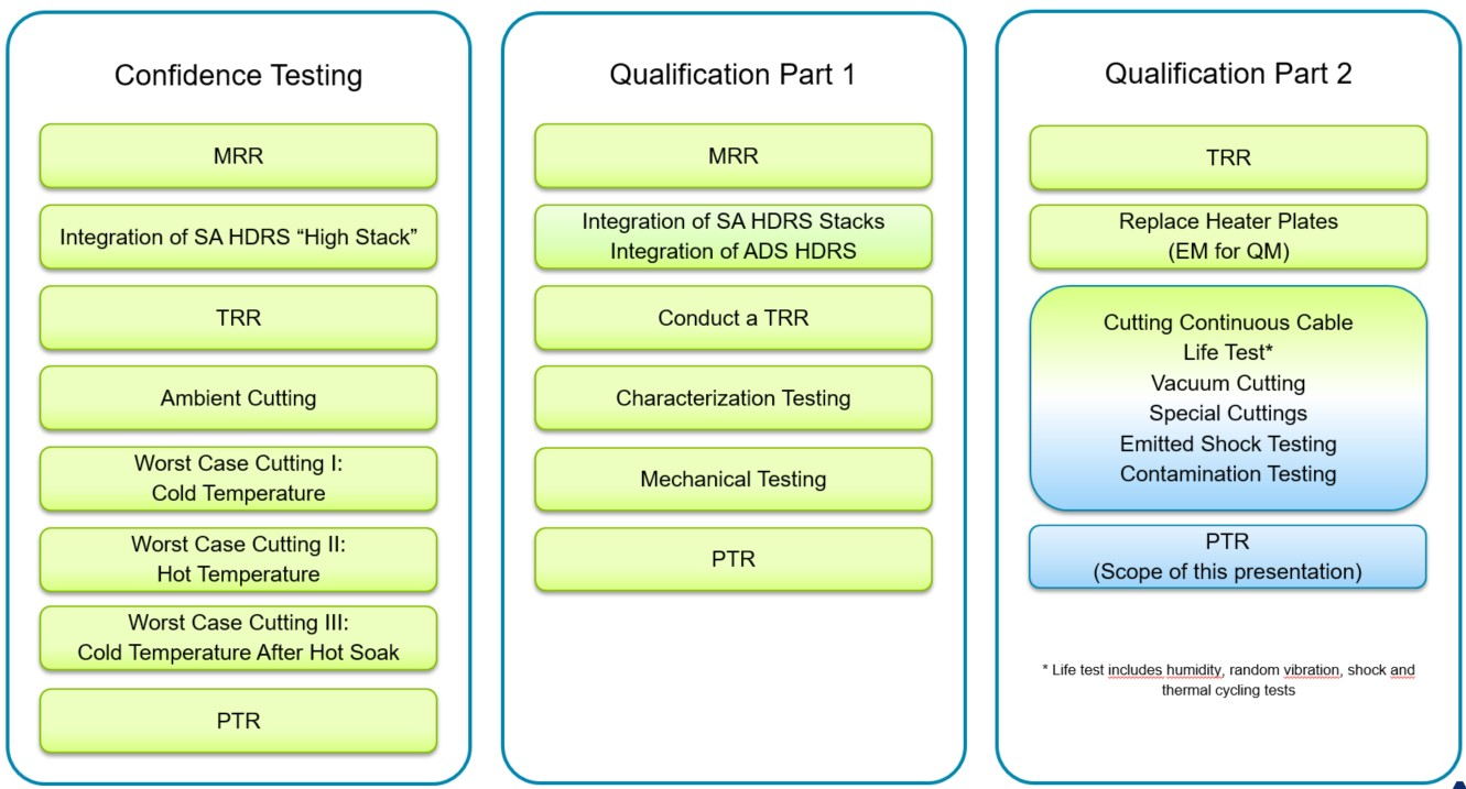
In this project, all issues Airbus DS NL encountered were resolved, all tests were completed and the results were reviewed with ESA and with the two lead (internal) Solar Array customers.
The NELS product offers the following key benefits:
- Ultra-low release shock
- Extended thermal envelope
- Higher pre-tension than ARA mk3 HDRS, up to 15kN
- Able to release after a time to reach GTO
- Competitive pricing
- High reliability (leveraged from Airbus DS NL’s extensive experience on hold down and release systems)
- Tested up to failure. Worst-case test performed that have improved the design and shown its abilities to release under worst conditions.
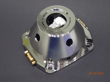
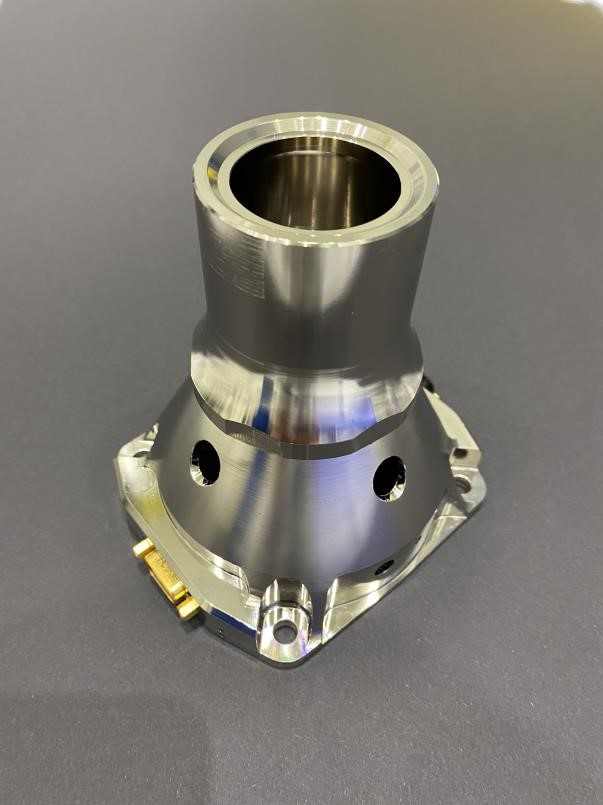
The NELS mechanism is functionally very simple at top level. It is designed to provide a structural interface to deployable structures with the spacecraft during launch operations and to release them when in orbit.
Two main drivers for the system become clear when looking at the physical architecture of the NELS mechanism. Those are the main structure with an interface to the spacecraft, and the cable structure.
The cable structure comprises of the cable, the end fittings on the top and the bottom of the cable, closing the load patch through a dedicated section of the structure. Internal to the structure the Vectran cable is exposed to two (main and redundant) thermal knives that each can cut through the cable in an angular motion when the knives are heated up.
The load path of the cable structure interfaces with the part of the structure that interfaces with the S/C structure.

Above are the key components depicted of the NELS mechanism: the structural elements and the release elements.
The structural elements were tested under worst-case qualification conditions to demonstrate it could withstand the applied loads while maintaining the required pre-tension through the cable and the structure. In the next test phase, the properties of the cable cutting and the properties of the thermal knives were subjected to these worst-case conditions.
Further features include:
- A redundant release switch
- Features that allow to easily replace the cable
- Connection to the Space Craft systems via redundant Space qualified connectors
- White cap for thermal protection
Increased demands from the S/C applications, including satisfying higher margins of safety, and a larger temperature range, require a re-design of the existing ARA Mk3 solar array design.
Therefore, the NELS development had the approach to extend the pretension to 15kN with a design that that has a high level of similarity with the existing ARA mk3 design, and to increase the temperature envelope.
In summary, the NELS project covered the following steps:
- Build up the Ground Support Equipment, both mechanical and electrical suitable for the qualification tests
- Build-up 3 NELS configurations
- NELS qualification test, comprising of:
- Restraint cable proof loading. Restraint cables are proof-loaded at a level higher than the actual load in order to remove setting effects.
- Restraint cable characterization of ultimate load in ambient pressure and room temperatures thermal conditions. Tests are performed on 2-panel and 5-panel Solar Array restraint cables and Antenna Deployment System (ADS) configuration restraint cable.
- Restraint cable shelf life test. Determine ultimate load as function of shelf life time.
- Long-term storage test of pre-tensioned NELS stack indicating pretension reduction over times of pre-tensioned 5 panel restaint cable (190.5 mm).
- Thermal knife moving torque and friction are measured in vacuum in hot and cold conditions.
- The mass of all parts and sub-assemblies is measured. o Insulation and conductivity tests are performed on the NELS system.
- The NELS system is mechanically characterized by the following tests: Stiffness test of bracket and conocal bracket and cup-interface adapter.including thermal washers
- Canting test
- Sliding test
- Snubber preload test
- Random Vibration test
- Shock test (emitted shock)
- Shock sensitivity test (absorbed shock)
- Life testing ‘test as you fly’ approach.
- Repeated cable installation simulation the ground environment. o Humidity test. o 20 TVAC cycles simulation Geostationary orbiting. o Cutting and release in vacuum at hot and cold conditions.
- Several cutting tests were performed to qualify different cutting conditions:
- Cutting with thermal gradient over the structure
- Cutting in ambient pressure Cutting in vacuum at room, hot and cold temperature with 20V heater plates
- Cutting in vacuum with interrupted power (3 times interrupted)
- Starting current in vacuum under cold conditions for temperature thermal knife. (max. power current level)
- No fire power in vacuum
- Cutting with current limited of 1.5 Ampere
- Contamination (particle and molecular) measurement during cutting with ‘whiteness plates’. Whiteness plate are analyzed on contamination content.
- Simulation of transfer orbit toward geostationary orbit by electro propulsion in 6 months. Simulated by hot soak testing and cutting of restraint cable
- Test reporting
- Final project reporting
- Conducting the Qualification Review
All activities in the ARTES 3-4 project are complete. In this ARTES C&G phase, Airbus DS NL has qualified the NELS design. At the end of the qualification test campaign the NELS product is considered flight qualified and ready for first application programme implementation.