-
StatusCompleted
-
Status date2015-03-05
-
Activity Code1A.071
The objective of this study is to examine the application of OBFN to satellite reconfigurable antenna systems and identify the benefits of this technology. This is carried out in the following manner:
- Identification of the needs for OBFN and how it would fill the gap left by conventional technology solutions.
- The identification of missions that would greatly benefit from the inclusion of re-configurable antenna schemes.
- Identification of applicable OBFN technologies with a selection of the preferred technology based on a set of agreed criteria.
- A detailed assessment of the selected technology against the earlier identified mission requirements.
- A definition of the development strategy for the chosen OBFN technology, and analysis of the commercial benefits of this technology.
The overall logic of the study is shown below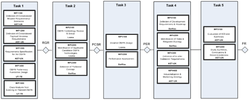
For the proposed designs, there are several technological challenges that need to be addressed before a fully functional OBFN can be fabricated. The most important challenges include
- Power consumption,
- Coupling two different waveguide technologies together, i.e. coupling InP to TriPleXTM,
- Fabrication of a full wafer sized TriPleXTM chip,
- Fabrication of a large InP chip.
Size of Optical Chip
Much attention over the past few years has been focussed on the inclusion of flexibility in communication satellite payloads.
A most attractive component in support of flexibility would be a re-configurable antenna system, which would enable the satellite to change its coverage to follow changes in traffic distribution or respond to new, developing market demands. The most flexible of such antenna systems are based on Array Fed Reflector (AFR) or Direct Radiating Array (DRA) architectures. These may use hundreds or thousands of feed elements with interconnectivity provided by a complex beamforming network. Beamforming may be provided either digitally, as in the case of the Inmarsat 4 series of satellites, or using analogue means, for example the Boeing Spaceway scheme.
A fundamental issue with digital beam forming is limitations related to the mass and power requirements of the digital processor, which can grow quickly with the number of control points. Analogue versions can be constructed. The problem with these is the insertion loss, which increases with the number of antenna elements, resulting in the need to incorporate embedded amplifiers within the BFN to maintain signal powers at a useable level. The beam former may also become unmanageably large and complex.
Because the beam forming is carried out optically, save for the RF/optical converters and dimensioning of elements internal to the optical chips, the same design and technology could be used for the optical BFN for the full range of RF applications from L-band up to Ka-band and even higher frequencies. Moreover, individual chips could be considered as building blocks, with the BFN of the required scale and functionality built up from these blocks. Such an approach could be a means of providing beamforming networks of large scale and complexity at low cost and with practicable features such as low mass, power requirements and insertion loss.
System Architecture
The OBFN system of choice for the 144-element array antenna is a binary tree structure in TriPleX™ technology. This integrated chip technology provides compact and low weight functional modules. Cascading optical ring resonators are used to achieve seamless delays and can cope with the large 2 GHz bandwidth that is required.
In order to further reduce footprint, interleaving of the 256x1 OBFN binary tree has been proposed. This has resulted in the ability to manufacture 3 OBFNs on a 150mm-wafer. The full functional system requires 36 256x1 OBFNs. All 36 modules then make up a full beamforming system for up to 256 antenna inputs. This proposed design allows standardizing packaging against a 350µm–pitch BGA-grid.
The study addresses each Task1 to 5, and associated Sub-tasks, according to the Study Logic:
- Task 1 – identifies satellite mission requirements, with emphasis on those aspects impacting on the antenna design.
- Task 2 – commences with a review of the current status and planned development of OBFN technology. A trade-off is then carried out, and a preferred OBFN concept selected.
- Task 3 – involves a detailed design of the OBFN based on the preferred concept from Task 2, and with application of the BFN requirements derived in Task 1.
- Task 4 – the definition of the OBFN development approach with provision of a development plan, a technology Road Map and identification of risks with mitigation strategy.
Task 5 – evaluation of the commercial benefits with an indication of the corresponding Return-on-Investment.
Project has been completed. A wide range of potential mission scenarios were identified at the initial part of the study to derive a reference scenario for the optical beamforming.
The study has developed optical beamforming concepts that address this reference scenario. The study investigated nine different OBFN options and the pros and cons of each option was analysed. Two promising option were selected for further investigations.
Draft documentation was submitted on 30 June 2014.
Project was completed in July 2014.