-
StatusCompleted
-
Status date2017-01-24
-
Activity Code5C.205
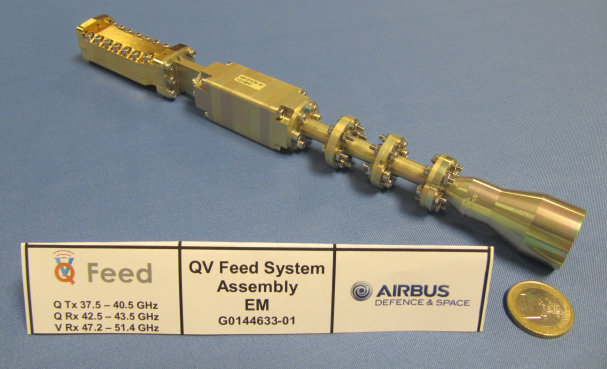
The objective of this project is to develop an Engineering Model Q/V-band Feed System (shown here).
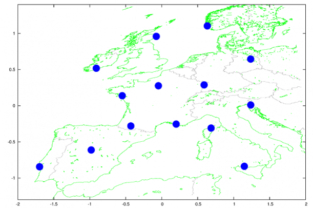
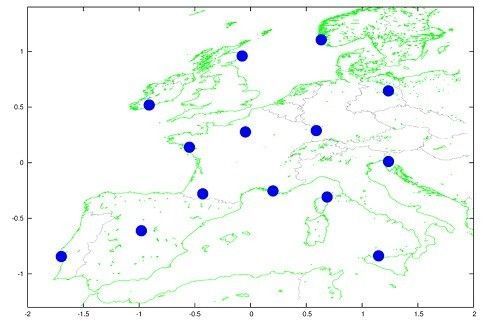
This product’s primary use is for gateway feed chains in multi-spotbeam antennas used in geostationary VHTS systems. The usage of the Q/V-band on the gateway link allows some spectrum to be made free for the Ka band user links. With the exception of the mission specific filters and feed horns, these feeds are generic and can be adapted for different missions. An example Q/V-band gateway coverage is shown above.
ACHIEVEMENTS
A Q/V Band Feed System Engineering Model suited to gateway feed applications in geostationary satellites has been designed, built and tested to suit a minimum feed spacing of 26mm.
The mechanical design of the feed successfully meets this feed spacing requirement and conventional machining techniques are employed to yield a robust and cost effective design.
The modular design consists of a wideband polariser and OMT for the core polarisation network, which operates in both LHCP & RHCP over the full range of Q/V-band frequencies available to FSS missions. The core polarisation network is augmented with a project specific horn and triplexers for the full feed system (EM) developed here.
The measured feed satisfies the return loss, isolation and axial ratio requirements, displaying an excellent agreement with predicted performance. An axial ratio of <0.4dB is achieved over the full Q/V band, with an isolation of >31dB between LHCP & RHCP ports.
The purpose of this activity to develop a Q/V-band feed system (EM), suited to gateway applications in telecoms VHTS systems, was achieved.
To meet the requirements of cost effective Q/V-band antenna geometries using smaller reflector sizes, the feed design has to accommodate a potential minimum feed spacing of 26mm.
The generic Q/V-band frequency plan and the selected filter frequency plan is shown below:
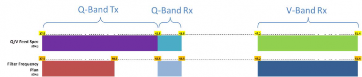
Q/V Feed Frequency Plan
Essentially, the feed has to work in dual circular polarisation in Q-band from 37.5 to 43.5 GHz, and in V-band from 47.2 to 51.4GHz. The requirements are further complicated by some of the Rx frequencies being assigned to the top of the Q-band adjacent to the Tx frequencies.
Feed architecture and complexity are a serious consideration for meeting these challenging requirements.
SYSTEM ARCHITECTURE
Following an initial feed architecture trade off and breadboard phase for critical feed components, a generic wideband feed architecture has been selected for full EM feed development. This comprises a wideband feed horn, wide band polariser, wide band OMT, and a pair of triplexers to accommodate the most challenging filter frequency plan.
This new feed product extends telecoms satellite capacity by using Q/V-band for gateway links and maximising the Ka band spectrum for broadband telecommunications (up to 1 Terabit).
A Q/V-band feed system therefore offers a competitive advantage and is a differentiating technology, as well as benefitting the end customers.
The Q/V-band feed system provides both RHCP & LHCP functions over the full transmit and receive bands, with an axial ratio performance of <0.4dB (XPD >32dB). An isolation of >31dB is achieved between oppositely polarised ports. Feeds can be spaced as close as 26mm apart, enabling smaller reflector sizes (e.g. 2m), and lower F/D ratios to be used in the antenna system architecture.
The core polarisation network is generic and covers the full Q/V-band frequency plan. Only the filters and the horns may change between missions. Because of the modular design approach, maximum flexibility is achieved with minimal project specific adaptation required.
SYSTEM ARCHITECTURE
The initial phase of the project consists of a feed architecture design trade-off; the results of which are presented at a Baseline Design Review (BDR). After the BDR, a breadboard phase covers the design of critical components to support the candidate feed architectures. At the Mid Term Review (MTR), the results of the breadboard activity are reviewed and the final feed architecture is selected for the full EM feed development in the final phase and tested for RF performance. The final report is presented at the Final Review.
The project is complete.