

-
StatusCompleted
-
Status date2020-02-04
-
Activity Code4B.065
Despite technology improvements, the current generation of European bi-propellant reaction control thrusters are not optimized to meet the increasingly stringent spacecraft pointing requirements. Significant improvements to the performances of the current sub-systems may be obtained with a lower thrust reaction control thruster with a smaller and more robust minimum impulse bit capability.
The minimum impulse that can be delivered by a thruster is a function of the minimum achievable pulse duration at a certain thrust level. The minimum impulse bit (MIB) is a measure of the smallest control torque that can be commanded to the satellite using the thruster. The steady state thrust level of a typical European bi-propellant RCTs is 10N. These engines have been widely used with on-times as low as 5 ms to give a MIB for fine pointing control. In this regime however the engine combustion is incomplete. This leads to a disturbing increased build-up of plume contaminants. However, the trend towards increasing antenna size and smaller spot beans in telecommunication platforms is driving the need for a continuous improvement in the spacecraft pointing accuracy.
Two options are available at system level to address this issue: Change the accommodation of the current 10N RCTs to reduce the moment arm, or implement a lower thrust RCT with a lower impulse bit in the same accommodation. From the system point of view the latter option is to be preferred.
As the present study demonstrates, current RCTs can be down scaled to meet this need. Low thrust RCTs have been validated in the past. Therefore, thrusters of this kind are expected to represent the natural evolution of current designs. Indeed mixed thruster configuration in general is a re-emerging issue as the first generation telecoms satellites had mixed thrust level RCTs. Optimizing the thruster selection for its location and required operations on the spacecraft (Station keeping, torque control, apogee back-up or pointing) could present opportunities to optimize budgets with a small impact on the spacecraft configuration.
Basing on the excellent performance of the 10N thruster, Airbus DS attempted to reduce the thrust level of bipropellant thrusters as far as possible below 10N, with the objective to achieve a higher pulse capability in the lower impulse range through higher combustion efficiency. Results of this investigation emerged, and took form in a new low level thruster in the range of 3 to 5N. The main intention going further down with the thrust level was to improve the performance of bipropellant thrusters, in order to take advantage of the higher specific impulse in comparison e.g. to monopropellant thrusters. That is to say, saving propellant and lowering the potential disadvantages due to combustion residues. This is driven by the continuous improvement demand in the spacecraft pointing accuracy and efficiency, and thus enlarges the application spectrum of a pure bipropellant propulsion system.
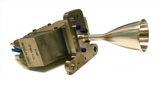
Figure: S4-3 Thruster EM1
Although further development of this chemical RCTs is essential to keep the lead wrt the continuous increasing customer demands, increased minimum impulse bit performance has been demonstrated on this thruster.
The Airbus DS S4 thruster is a bipropellant rocket engine delivering a nominal 4N (0.9lbf) thrust using the storable propellants monomethylhydrazine (MMH) as fuel and nitrogen tetroxide (N2O4, MON-1, MON-3) as oxidizer. As a result of reduced thruster dribble volumes and high combustion efficiency, the thruster is designed to achieve high efficient minimum impulse bits and to reduce the plume contaminant production.
The S4-3 is a new engine of a 4N bipropellant RCT family equipped with a dual seat valve (Airbus DS), designed for both, long steady state and pulse mode operation, operating in both pressure regulated and blow-down mode. Its key design features are based on the well proven 10N engine and on an earlier 4N thruster concept explored for the aim of the former CRAFT mission.
The thruster design includes all features which make Airbus DS’s bipropellant thrusters outstanding since some thirty years:
- Flight proven, from the shelf components: Due to a common thruster interface, the 4N engine shares its flow control valve options with Airbus DS's 10N and 22N bipropellant thrusters. This includes the metallic sealing and trimming components.
- Double cone vortex injection: As derived from Airbus DS's bipropellant thruster family up to 400N, the 4N thruster implements an injector where the two propellant components are sprayed by two coaxial swirl atomizers into the combustion chamber. This guarantees for a very well balanced coolant distribution and thus balanced temperature distribution throughout the entire chamber and an optimum propellant atomization and mixing and thus optimum reaction and thruster performance.
- Super-alloy heat barrier: In order to minimise dribble volumes, hence maximise the pulse mode performances, the injector thermal isolation is performed with a fuel film cooled conduction barrier made of a high resistant NiCr based super-alloy. The current engine is designed without an additional bird cage heat barrier.
- Uncoated Platinum Alloy Chamber and Nozzle: Because Airbus is following the strategy of not using coated materials since the very beginning of its space propulsion activities, the thruster employs a platinum-based alloy for the hotter throat area. Protective coating of high temperature resistant but oxidizing materials have always been deemed as solving one problem by creating a new one. Defective coating may rapidly lead to failure of a thruster. Thermal cycles of a million of thruster pulses during a satellite life can cause coating defects, as can improper thruster handling during AIT. Application of thermal sensors on chamber and nozzle during ground tests are considered to be prohibitive. All those potential constraints of a coated chamber material are not encountered in conjunction with Airbus DS’s Pt-chamber approach.
In agreement with ESA's SOW, the work was divided in following main tasks and phases:

Demonstration test completed (vacuum hot firing).
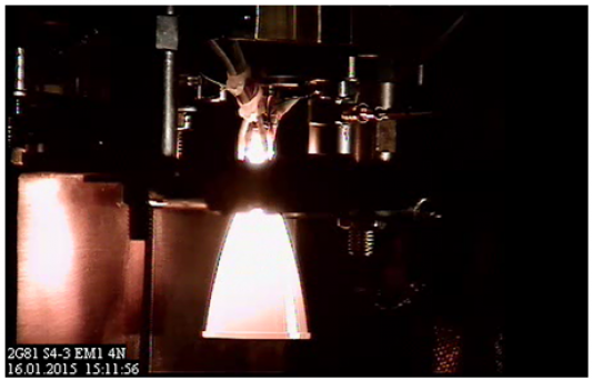
Figure: S4-3 EM1's maiden ignition
The S4-3 EM1 design demonstrated a very effective and steady behaviour over a wide inlet pressure range, for both, steady state and pulse mode firing. The thruster reached a specific impulse of up to 298 s at 4.8N steady state thrust. In its lowest impulse range, the S4 demonstrated up to twice the efficiency of a S10 thruster for a 15 mNs impulse.