-
StatusCompleted
-
Status date2022-08-24
-
Activity Code5B.165
The goal of the BEAMSAT-2 project is to study, design, realise and test a cost-effective high gain antenna, with a goal gain of G ~ 30 dBi, for inter-satellite links between CubeSats.
The application scenario for the intended development is a 59.3-71 GHz inter-satellite link that could operate in frequency-division full duplex or time-division simplex/duplex.
The reference scenario foresees the use of a link between satellites that are in the same orbital plane and separated 2000 – 4000 km from each other; the goal is to obtain a data rate between 1 – 3 Mbps.
The result of the BEAMSAT-2 project is an Axially Displaced Ellipse (ADE) antenna. The system is characterised by a high gain >30 dBi on the overall bandwidth 59.3–71.0 GHz, occupying a total volume <0.5 U, a mass <100 g. The pointing system provides an azimuthal orientation of +/-180°, zenithal orientation: +/- 40°.

The key challenges of the BEAMSAT-2 project are technical:
-
RF performance: >30 dBi on the overall bandwidth 59.3–71.0 GHz, axial ratio <1.2 dB, sidelobes level <-13 dB;
-
Miniaturisation: total volume <0.5 U, mass <100 g;
-
Pointing system: azimuthal orientation of +/-180°, zenithal orientation: +/- 40°.
In addition, thanks to the efficient application of 3D printing techniques, the overall production cost is kept very low.
The market for small satellites is currently booming on a global scale. Growth of the telecommunication field is even greater than was seen in the early years of Earth Observations. One of the capabilities that could allow telecommunications applications from a small satellite system is the Inter-Satellite Link (ISL). For such links, high gain antennas are needed.
Today, a low-cost ISL between CubeSats can be achieved at GHz frequency bands through miniaturized design and moderate costs. Indeed, technology for small satellites can already be implemented by means of COTS components. In particular, with respect to lower frequency bands, the higher GHz bands:
-
are available and scarcely used;
-
allow limited costs;
-
allow higher spectrum or bandwidth availability;
-
allow expected higher energy at the receiver.
Currently the BEAMSAT-2 Axially Displaced Ellipse (ADE) antenna represents one of the first developments of a miniaturised High Gain Antenna operating at 60 GHz that may serve CubeSat missions.
The goal is to serve transceiver systems to obtain a data rate between 1 – 3 Mbps.
The BEAMSAT-2 is an Axially Displaced Ellipse (ADE) antenna, made by a reflector of diameter D=80 mm, a sub-reflector of diameter d= 9.6 mm and a F/D=0.3 ratio, and a feed. The figure below represents the final antenna design.
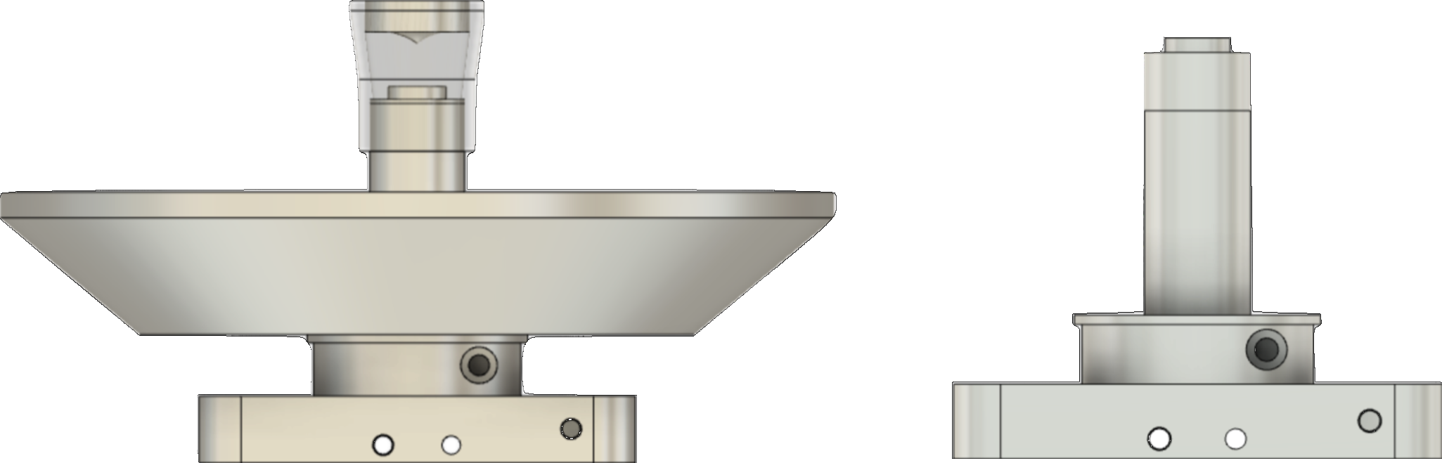
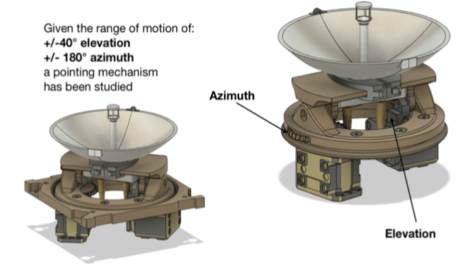
The pointing system allows the antenna to reach ±40deg in elevation and ±180deg in azimuth. Furthermore, the system is able to continuously point the antenna in the azimuth range of 0-360deg. The azimuth pointing is achieved by a pinion acting on an internal gear (figure below) whether the elevation pointing is achieved by a rod acting between the motor and the antenna support.
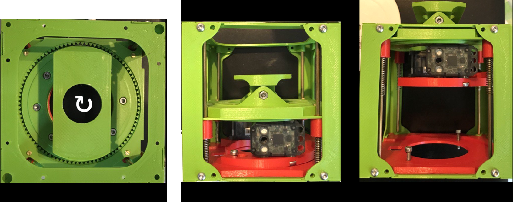
The antenna and pointing system are located inside a CubeSat unit. In order to be able to freely operate the antenna pointing, a deployment system is necessary. For this purpose, we developed a deployment system driven by 4 compression springs.
The system, locked by a mechanical joint, is activated by the rotation of the pointing system base, see figure below (left).
Activating the pointing system by rotating the base of the pointing system (azimuthal pointing) allows one motor to be used for several functions, reducing the mass and number of components used. The great advantage of this solution is certainly the possibility of using the pointing system to activate the deployment system, thus saving in terms of mass, additional components and system complexity. Turning the azimuthal pointing in a counter-clockwise direction releases the mechanical constraint, thus allowing the springs to bring the pointing system and the antenna into its final position.
The figure also shows the deployment system before activation (in the middle) and after activation (right).
The project is organised in six tasks:
Task1 Finalised Technical Requirements
-
Finalised technical Specifications
-
Implementation Feasibility
MS1 Requirement Review
Task2 Antenna System Concept and Technology Selection
-
Antenna System Concept Review
-
Manufacturing Technologies Review
-
Proposed Antenna System Solution
Preliminary Design Review
Task3 Antenna System Detailed Design & Analysis & Prototype
-
Antenna System Thermal and Mechanical Design
-
Antenna System Detailed RF Design
-
Sensitivity Analysis
-
Antenna System Prototype Design
MS2 Critical Design Review
Task4 Antenna System Prototype Manufacturing
-
Manufacturing Subsystems
-
Assembled Prototype Antenna System
-
Test Procedures
Prototype and Test Readiness Review
Task5 Antenna System Prototype Testing
-
Tests of Antenna System Prototype
-
Update Antenna Prototype
Task6 Antenna System Development Plan
-
Overall Evaluation
-
Antenna System Development Plan
MS3 Final Review
The BEAMSAT-2 project is aimed at designing, producing and testing the prototype of a “Cost-Effective High-Gain CubeSat Antennas”. Currently, the first five tasks are accomplished, tests confirmed the positive results of the simulations.
The last task is aimed at providing the overall evaluation, the roadmap and the antenna development plan. We identified several potential additional antenna solutions and applications that can profit from the BEAMSAT-2 results. PICOSATS is now looking towards the engineering of the full system, especially of the pointing system, to arrive at a launch opportunity. In order to achieve that, PICOSATS is also planning to develop a transceiver working at these frequencies.