-
StatusCompleted
-
Status date2017-01-11
-
Activity Code4A.030
Phase-2 of this programme covered the evolution of the TTC product taking into account findings from the first qualification campaign and aimed to accommodate market requirements that were not previously addressed. The changes implemented in Phase-2, which required a full qualification campaign were as follows:
- Increase the life expectancy of the TT&C from five years to seven years
- Introduction of a second (redundant) data interface for cross strapping in redundant configurations
- Introduction of a hard/soft reset and restart feature for mitigation against SEEs
- Increase of the maximum RF output power capability from 2.2W to 5W, with configurable power levels in 1dB steps
- Introduction of an automated test methodology
- Upgrade of the TT&C components to meet ESA class-3 requirements
 Ultimately, the main objective of the programme was to qualify the transceiver and antenna filter system for use on an ESA programme. and provide a baseline product that can be utilized on other missions requiring an S-band TT&C / downlink transceiver.
Given that the initial design of the equipment was based on COTS components and the goal was to satisfy the requirements of an ESA science mission, the project had to overcome numerous challenges during development.
The implemented updates included a complete re-evaluation of the equipment design and identification of areas that needed to be further validated by additional testing or design modifications. Two major areas that required significant effort were the cost driven component selection and the radiation tolerance of the equipment.
The updated qualification campaign involved both TiD testing and SEE/SEU testing at sub-system level, aiming to characterize the equipment behaviour/tolerance under higher radiation levels.
In line with the original goals, the project has achieved its objectives and now offers the following benefits:
- The TT&C lifetime has been increased from five to seven years through two major activities;
- swapping out components for established high reliability parts
- swapping out low radiation resistant parts or including mitigation circuits to improve radiation tolerance.
- The MTBF is now calculated to be 11.8 years.
- The TT&C now incorporates dual redundant interfaces. The MODE, HK and TC are cold redundant, meaning that data can be sent to/from both interfaces at the same time, while the TM interface is hot redundant, so the relevant transceiver must be commanded to accept TM data when required.
- A soft and hard reset interface has been added to the transceiver. The soft reset is implemented within firmware and ‘reboots’ the TT&C under command of the OBC. The hard reset has been implemented via a dedicated hardware line and removes secondary power within the unit. This is a powerful mitigation strategy for clearing latch ups due to radiation etc.
- The maximum RF output power capability of the transceiver has been increased to 5W. The transmit RF power level can be pre-determined and further varied via OBC control commands. .
- An automated test methodology has been implemented, allowing faster turnaround time for testing each unit.
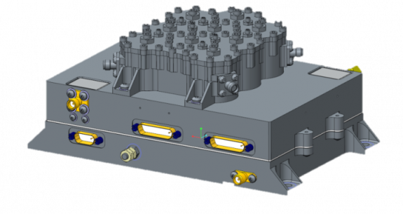
The Honeywell S-band TT&C transceiver is a single integrated module capable of both receiving uplink telecommands from a ground station for satellite control and receiving telemetry data from the satellite OBC for modulation and transmission back to the ground station.
The transceiver is based on a Software Defined Radio architecture and is configurable into a variety of operational states via OBC originated MODE commands. It can be programmed with a variety of different receive and transmit modulation schemes:
- Receiver: sub-carrier BPSK at rates of 1, 2, 4 and 8 kbps, SP-L and BPSK on-carrier rates of 8, 16, 32, 64, 128 and 256kbps.
- Transmitter: programmable BPSK (up to 1Mbps), QPSK and OQPSK (up to 6Mbps)
It provides health and status data to the OBC via a housekeeping (HK) interface. The MODE and HK interfaces work on an asynchronous interface over RS-422 while tele-command and telemetry are synchronous over RS-422.
The band pass antenna filter is configured as two independent band pass filters (transmit and receive) in one housing for separate TX / RX antennas. Alternately a diplexer variant can be supplied for TRX antenna systems. The transmit filter has been designed to ensure that the TT&C will comply with ECSS regulations concerning RF emissions and that the transmitter section of the transceiver will not interfere with its and other on-board receivers.
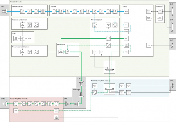
system architecture
The transceiver is divided into three modules:
- Modem module: This implements the receiver and the transmitter.
- Receiver: The S-band receiver consists of a two stage super-heterodyne architecture, with factory-adjustable receiving frequency from 2025MHz to 2110MHz. The first stage is implemented in RF electronics, while the second stage is a logical implementation in firmware.
- Transmitter: The telemetry data stream enters the FPGA via the telemetry data and clock lines and is mapped onto modulation symbols by the firmware. A numerically-controlled oscillator is used to pace the symbol stream into a pulse shaping filter. The output stream amplitude and phase is adjusted to compensate for gain and phase imbalances in the analogue circuitry.
- Power Amplifier module: The RF signal from the modulator is fed into a SSPA, which uses a GaN transistor final stage. This provides the SSPA with very high efficiency allowing for mission power saving. The power level can be adjusted in-flight by 1dB steps, which provides system flexibility to optimise the spacecraft power and link budgets.
- Power Supply Unit module: The power supply unit contains independent DCDC converters for the transmitter and receiver. EMC compatibility with the primary power bus is ensured by implementing input EMI filters.
The development was structured into four main areas of activity:
- System re-design of the TTC equipment
- Manufacture and assembly of the EQM unit
- Test methodology updates including the development of an automated test system
- Full flight qualification including thermal testing, TVAC, EMC/ESD, shock & vibration, SEE/TID radiation testing
The qualification schedule was aligned to the ESA CHEOPS mission requirements with an expectation that this would be expanded to further ESA missions after qualification.
Complete
The main aims of the 2nd phase of the CETB programme were to increase the functionality of the transceiver, characterise its performance and address the need for a high quality, lower cost TT&C unit. The acceptance of the equipment by an ESA mission (CHEOPS) was a secondary aim that proved the suitability of the equipment for an ESA science mission. ESA’s input to this programme was invaluable and helped Honeywell’s technical experts complete a successful qualification campaign.