-
StatusCompleted
-
Status date2021-01-28
-
Activity Code5B.161
The main objective of this ARTES 3-4 proposal is to complete the necessary activities for flight qualification at sub-assembly level of the components of the ELSA + Active In-orbit Reconfigurable Rx Antenna in Ku Band with capacities for Beam Hopping and Geolocation and mitigation of interferences. The proposed antenna is a significant evolution of the ELSA antenna on board the AG1 Small Geo platform, also partially funded by ESA. The ARTES 3-4 program proposed herein is the continuation of an ARTES5.2 program finished on December 2015. The main objective of that program was the detailed design and prototyping of the components identified as critical for the ELSA+ antenna, reducing this way the associated risk of the overall program.
In addition to the critical elements identified, this contract also covers the Qualification of a partial Structural Qualification Model (pSQM) and the RF and Thermomechanical analysis at antenna level.
The customer expectations identify needs and associated challenges in the design and technologies versus the heritage:
- The bandwidth required covers the full FSS band, more than 2 GHz, meaning a strong evolution in all the RF components in the path, the Passive beam-forming network (BFN) elements, the active control module (MCCM), custom MMICs and the radiating element. The significant update of heritage building blocks required a new qualification which was covered by this project.
- Dual polarization operation imposes a drastic evolution from tile implementation to dual panels which was considered critical at the beginning of the project required a partial Qualification Structural Model (pSQM). The antenna electronics were almost double as well.
- Beam Hopping allows the adaptation of the satellite resources to the traffic demand in a very large coverage (covering different service areas). The ELSA+ implementation is compatible with the DVB-S2X standard and has required the adaptation of the antenna electronics and the custom Digital ASIC, which have been designed and qualified in this project.
- Geolocation is a fully new functionality, requiring significant development in both the space segment and the processing ground software. The design and qualification of dedicated hardware units, both RF (GEO horns, MCCM based downconverters, IFSAM hybrid for variable gain amplification) and Geoloc electronics.
The dual pol and the extended band objective of the development are motivated by the huge increase in capacity that can be offered to the customer. The increase from 4 to 8 beams thanks to dual polarization implementation and the wideband operation up to 1050 MHz, allows a capacity up to 8400 MHz provided by ELSA+ antenna system.
The Beam Hopping aims at the adaptation of the satellite resources to the traffic demand in a very large coverage. It is beneficial since the beam is shared in time between different service areas according to expected traffic demand over the time. Besides, this concept of operation allows adjusting the beam-width to the specific service areas improving link performances (satellite EIRP and/or G/T).
Geolocation allows to monitor the position, power and polarisation of interfering emitters on ground with a granularity below 2 MHz within the FSS band. Knowing the position of possible non authorised emitters or intentional jammers allows the operator to take corrective actions, such as pointing, shaping or nulling (feature already available in the product) in the affected direction.
All this features allow offering the customer more capacity, flexibility and interference immune product, currently not available in the European market.
An on-board unit which provides the multibeam, enhanced with dual-polarization and extended bandwidth capability for the required G/T, with the pointing, nulling and shaping capability, and will perform interferences detection and beamhopping.
An on-ground unit to control the antenna system and also to process interference information in order to mitigate them properly, and to fully exploit the system features.
The on board HW architecture has been designed to comply with the new market needs. At the same time, the modularity approach gives flexibility to adapt to other requirements by means of growing up the number of elements or redesigning the affected units.
.
The architecture and main assemblies developed in the project correspond to the on-board unit including:
Rx antenna
- Radiating chains provide RF signals which are connected to the input of the MCCMs.
- Each MCCM-Rx manages 4H or 4V signals. The signal coming from the radiating elements is amplified in this unit, prior to be divided by 4 in order to get the contribution for the 4H or 4V beams.
- After the MCCMs, the signal combination is done, 4:1, is implemented into the MCCM subassembly, and the next level of combination 21:1 is implemented by means of 6 combiners of 5:1.
Beam-hopping
- Beam-hopping synchronization by means of a sync pulse received by ICU, which delimits the instance of changes on the Antenna Beam Switching Time Pans (ABSTPs).
- Then ICU handles the proper loading of ABSTPs to the MCCM digital ASICs, which control the RF active devices.
Geoloc
- Sensors (radiator+filter+transition) of the incident signals and input filters reject signals outside interest-band
- Inside MCCM-GEO the signals are down-converted to IF in order to operate in the input bandwidth of the ADC
- Afterwards, inside the IFSAM module, signals are conditioned to the ADC
- ADC digitizes the signal of ach sensor.
The activity allows for risk mitigation on the development for a commercial telecom project, and is the first step of a global plan defined in 3 steps:
- Step I (this ARTES 5.2) covering the work up to the prototyping of the antenna subassemblies identified as critical for the enhanced antenna system, and architecture and system definition
- Step II (ARTES 3-4) covering the detailed design, manufacturing and qualification phase (out of scope of this activity) of the antenna system subassemblies.
- Step III (PFM) covering the detailed design of the PFM, the production of the FM subassemblies followed by the integration and test campaign.
The ARTES 3-4 project has been coordinated with Eutelsat Quantum PPP project, where ESA has reviewed together with EUTELSAT the proper design at CDR milestone and review the qualification of the subassemblies in the QR milestone.
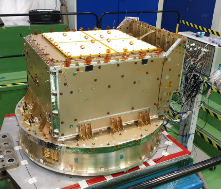
ELSA+ antenna is qualified, as well as the building blocks and required technologies for the implementation of the product.
The ELSA+ antenna has been tested on board of the Eutelsat Quantum satellite and is ready to be launched in Q1 2021.
COMLPETED.