
-
StatusOngoing
-
Status date2016-08-08
The key objectives of the project are as follows:
Barnard Microsystems Limited (BML) is a SME based in the UK that is developing mid-sized (6m wingspan) Remotely Piloted Aircraft (RPA) for use in civilian applications throughout the world:
- in oil, gas and mineral geophysical survey work;
- in oil pipeline monitoring;
- in land and maritime border patrols.
In these missions, the RPA spends most of its time operating Beyond Line Of Sight, often in areas with no communications infrastructure. To maintain the legally mandated link between the Pilot-in-Command at the Remote Pilot Station and the RPA, a satellite data relay service must be used.
In the UASatCom IAP Feasibility Study, ESA Contract Number 4000103768, we identified the Inmarsat SwiftBroadband satellite data service as a suitable Command and Control data link between the RPS and the RPA. In the SURMON Demonstration Project 4000107665, we concluded that a phased array satcoms antenna that could fit within the wing of the RPA was required:
- to reduce the aerodynamic drag of the satcoms antenna;
- to increase the reliability of the antenna, relative to mechanically pointing variants;
- to reduce the cost of the satcoms antenna for use in commercial applications.
In this proposed 12 month ARTES 5.2 Feasibility Study, we aim to demonstrate the feasibility of:
- an L band transmit and receive, electronically steered, array antenna, mounted in the wing of our Inview RPA, for use with the Inmarsat SwiftBroadband satellite data relay network;
- a 5.8 GHz ISM and IEEE 802.11a (WLAN) band transmit and receive, electronically steered, array antenna, mounted in the wing (on the underside) of our Inview RPA for use in a wireless bridge link between the RPA and the Remote Pilot Station. This technology will also serve as a precursor to the proposed frequency band from 5.030 GHz to 5.091 GHz for use in a future RPA-to-satellite communications link.
Key issues
- Using a stacked element patch antenna array, get a suitable bandwidth with the correct lower and upper frequencies.
- Get as large an electronic sweep as possible, ideally 180°.
- Get antenna characteristics compliant with Inmarsat specifications.
- Interface the Cobham 325 SDU with the antenna.
- Electronically sweep the beam sufficiently quickly to counter RPA movements.
Expected Main Benefits:
- Less aerodynamic drag associated with an antenna embedded within the wings of the RPA.
- The fixed antenna array has no moving parts, and thus is more reliable than an antenna in which moving parts are used.
- The directional beam creates less interference in nearby antennas located on the RPA.
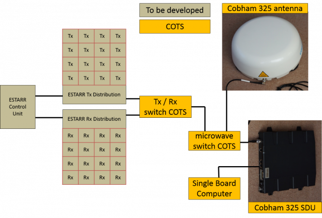
Figure 1: diagrammatic view of the ESTARR system.
The architecture of the ESTARR system is as shown in the diagram above:
- phased array configuration
- separate 4x4 Tx and Rx element arrays
- we are using the Cobham 325 SDU
Project Plan:
We have broken the Project into 5 Work Packages:
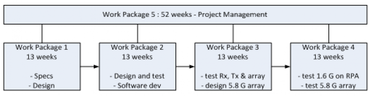
Figure 2: outline of the ESTARR Work Plan.
Project Kick-Off
- Monday 23 November 2015
Project Baseline Design Review
- Thursday 7 April 2016
- WP1 prototype design and exploitation business plan discussed and agreed upon.