-
StatusCompleted
-
Status date2015-08-31
The need for wider frequency bandwidths in multimedia applications pushes payload design toward higher frequencies. Recently, a significant frequency bandwidth has been allocated by the International Telecommunication Union (ITU) in the Q/V band for Fixed-Satellite Services (FSS), making these frequencies the most promising candidates for the near future broadband systems. From on-going studies investigating next-generation high-capacity satellite architectures, it is anticipated that a first step would be a GEO mission making use of Q/V band for the feeder link, while the user link remains in Ka band.
Within this frame, and under the ARTES 5.1 initiative, the European Space Agency has contracted to the team composed by HPS GmbH (as prime contractor), INVENT GmbH and TESAT GmbH (as sub-contractors), Cobham CTS Limited and other partners the development of an earth-deck antenna for feeder link applications in Q/V band (Frequency band Tx: 37.5-40.5 GHz, Rx: 47.2-50.2 GHz) to be embarked on a GEO communication satellite mission with high capacity requirements.
One of the objectives of the activity was to perform an antenna architecture trade-off to identify the most suitable antenna geometry for such an application taking into account RF and thermo-mechanical aspects.
As best antenna configuration a Gregorian offset geometry has been selected and validated with an EM (Engineering Model), including a representative feed chain.
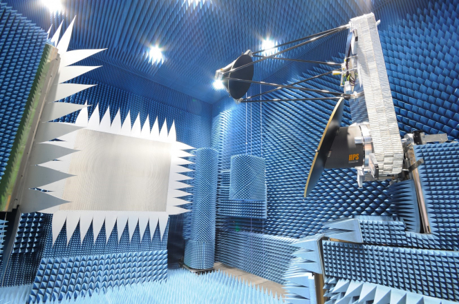
Figure 1: FLANT EM model during the RF test campaign (HPS GmbH)
From an RF point of view high isolation between all beams and low scan degradation for widely scanned beams had to be realized in a fairly compact antenna configuration.
From a mechanical point of view the high frequency band of the FLANT antenna requires very challenging tolerances of all the RF components (Feed chain, main and sub reflector). The design of the antenna, the processes adopted for the manufacturing, the assembly procedures, the measurement during the alignment phase have all required special care in order to achieve the very good performances measured on the RF test campaign.
The main benefit of a feeder link antenna operating in the Q/V band compared to Ka-band antennas is the larger bandwidth available to be used to spread fast telecom services channels such as voice, television, internet etc
SYSTEMS ARCHITECTURE
The FLANT antenna has Gregorian configuration (see figure 3) with 10 beams to illuminate 10 Q/V-band gateway sites within Europe (see figure 4). Two gateway clusters of five sites were identified covering the western and the eastern part of the area, with one site per cluster identified as back-up gateway for rain fade diversity operation.
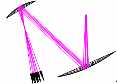
Figure 3: Ray path of all 10 beams of FLANT
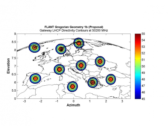
Figure 4: Rx Directivity contours at 50.2 GHz
The selection of the Gregorian antenna configuration is the result of a multidisciplinary trade-off analysis involving the main antenna fields:
• RF design,
• mechanical design,
• thermal design,
• thermo-elastic performances,
• accommodation (envelop, earth deck footprint, height).
The main and sub reflectors of the EM, having respectively a diameter of 1.2 m and 0.7 m, consist of sandwiches composed by Ultra High Module CFRP facesheets and Aramidic honeycomb core. It shall be noted that the adoption of an Aramidic core was decided in order to reduce the EM model cost and comply with the budget of the project. The flight model will be provided of a CFRP core. The main reflector is supported by a CFRP tube. The sub-reflector is supported by a dedicated tower composed by 6 CFRP struts and a triangular sandwich plate.
The two reflectors, with their respective supports, are installed on a sandwich baseplate (Al facesheets and Al honeycomb-core). The thickness of the baseplate sandwich of the EM model is much higher than the flight model. The reason is that during the RF tests the EM model is supported in a cantilever configuration, having the I/F to the Compact Range positioner coaxial with the main reflector tube. Moreover the baseplate of the flight model has CFRP facesheets.
In figure 2 is shown the EM model of the FLANT antenna during the alignment activities. The verification of the contours of the two reflectors, as well as the alignment of the main component (main reflector, sub reflector, feed and baseplate) were performed using a Laser Tracker measurement system.
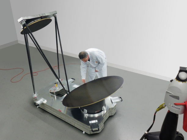
Figure 2: FLANT EM model during the alignment activities performed with a laser tracker (HPS GmbH)
The project was organized as follows:
- Task 1 had to consolidate the proposed mission using a Q/V-band feeder link antenna sub-system and the corresponding feeder link antenna requirements.
- Task 2, running in parallel to task 1, had to provide an overview of the state-of-the-art of Earth deck antennas and Q/V-band technology.
- Task 3 had to perform an antenna configuration trade-off and selection of most promising candidate and derive requirements at sub-system level.
- Task 4 had to provide the analysis at feed and antenna level and define the antenna EM to be manufactured.
- Task 5 is related to the hardware manufacturing.
- Task 6 covers the antenna EM RF testing.
Task 7 had to perform a review of achievement based on the measurement results and conclude on the feasibility of an Earth deck antenna suited for Q/V-band feeder link applications.
All the tasks have been completed.
The measurement of the EM model of the antenna has shown the compliance with margins to the requirements and an excellent agreement with the RF analysis performed taking into account the contour measurement of the reflectors and the alignment data (see Figure 5). This confirms the robustness of the mechanical and RF antenna design and validates the MAIT (Manufacturing Assembly Integration and Test) processes and procedures adopted by HPS GmbH and its partners for Q/V band antennas.
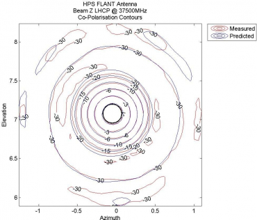
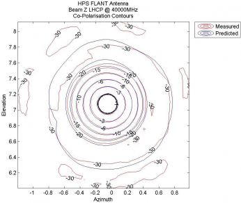
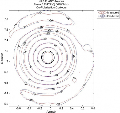
Figure 5: FLANT EM antenna, comparison of the measured and predicted co-polarization contours @37.5GHz (top), @40GHz (center) and @50.2GHz (bottom)