
-
StatusCompleted
-
Status date2017-12-11
-
Activity Code5D.027
FBG technology is gaining presence in various industrial sectors for measuring a wide variety of physical phenomena, such as temperature, pressure or strain. FBG sensors are engraved in optical fibres and each sensing element reflects a given wavelength when illuminated.
The present ARTES 5.2 project aims at providing a significant step forward towards the pre-qualification of the technology for space, providing redesign of both the FBG sensors and specially the interrogation unit electronics following space design techniques. The objective of this project is to develop, manufacture and characterize a full demonstrator, including sensors, fiber and interrogation electronics, up to TRL 5. The monitoring system includes redundancy to fiber cuts and the unit can be easily configured, being suitable to acquire different kinds of FBG sensors.
The design is based on space-qualified components when possible, while the non-qualified optoelectronic components have been identified within the project and a validation plan has been defined and implemented for each of these components.
An EM has been manufactured using equivalent components (military quality) and a pre-qualification testing campaign has been undertaken on the implemented prototype to validate it.
Although FBG technology is widely used in various industrial fields, it has not yet been developed for space applications.
The main challenge in this project is to adapt this technology following space design techniques at competitive prices versus current standard technologies. Key challenges:
- Optical elements of the system must be validated to withstand space environment for telecom satellites.
- System must be able to handle more than 100 sensors and acquire them cyclically in 100 ms.
- System must be stable in time and over different environmental conditions (mainly temperature, radiation and vibration) and provide timestamped data.
The main advantages of this technology are:
- Size and weight: FBGs are written inside the core of the fibre.
- Multiplexing of sensors in a single fibre, leading to a remarkable simplification of the spacecraft’s harness.
- Multi-functionality: a single fibre can embed sensors designed to measure different types of physical magnitudes, whilst the interrogator remains the same.
- EMI immunity: the physical magnitude is retrieved without the intervention of electrical signals. This allows measuring in antennas or in explosive atmospheres.
- Robustness against the length of the fibre: the accuracy is not affected by the distance between the sensing elements and the interrogating unit.
- Failure tolerance: in case of a fibre being cut, the sensing elements can be illuminated from the other side without performance degradation.
FBG technology has a clear advantage with respect to the classical sensor acquisition technologies for what concerns harness complexity (up to 20 sensing elements per fibre), power consumption (sensing elements are not stimulated by electrical power) and weight, while the accuracy of the measurements is comparable.
For a launcher or a telecom satellite these advantages would translate into:
- AIT process simplification - Increased number of sensors with reduced cabling, and improvements in terms of harness mass and complexity and MAIT effort.
- Possibility to incorporate thermal mapping in new areas not previously monitored (e.g. high EM field areas, RF antennas and components, fuel tanks…).
Key Design Features
- Compatible with the RTU2015’s standardized interfaces. It uses two slots of the RTU.
- Easily adaptable to other host units, since it requires just an unregulated 28V supply and an SPI connection.
- Up to 8 fibres can be interrogated, meaning up to 160 temperature-sensing points.
- A single fibre can contain several types of sensors.
- Low power, lightweight technology for sensor acquisition.
- Able to acquire physical properties in harsh electrical environment.
- Its ARM Cortex-M1 microprocessor provides a high degree of configurability, including individual customized curves.
General Features
- Control Interface (TM/TC): SPI bus
- Number of channels / fibres: 6 (extendable to 8)
- FBG sensors / channel: 20 (temperature)
- Voltage: 28 V ± 4 V
- Interrogation laser wavelength: 1,500 nm - 1,600 nm
Measurement Performances
- Sampling frequency: 10 Hz / 120 sensors in 100 ms
- Temperature measurement accuracy (-55ºC to +125ºC)
General calibration curve: ±1ºC
Individual (look-up table): ±0.2ºC
- Tolerant to one failure in each fibre
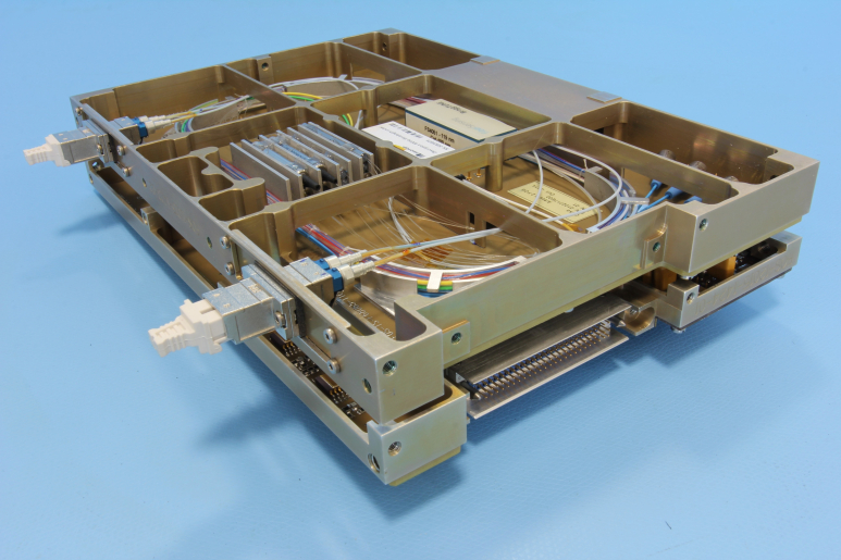
Budgets
- Mass: 1,200 g
- Volume (PCB: double Eurocard format):
(Height x Depth x Width). 160 mm x 233.5 mm x 52 mm
- Power Consumption (typical):
Standby, with no acquisition: 6 W
Operational, at room temperature: 9 W
Operational, whole temperature range: 12.3 W
Next figure shows a block diagram of the FOS system. It is composed by several elements:
- An interrogation unit (IU), which is broken down in two separate modules (FOS CONTROL and FOS OPTICAL)
- The external optical harness (OH), which interconnects the Fibre-Bragg-Grating FBG sensors.
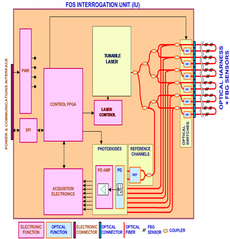
Main system architecture elements are:
- Tuneable fibre laser: sweeps the 1,500 - 1,600 nm range
- Reference channels: used to provide precise reference of the laser emission wavelength.
- Optical switches: used to support the one point fibre failure
- Photodiodes: perform optical to electronic conversion
- FPGA: it embeds the TM/TC management of the module, the interface with the serial communication bus and a micro-processor that is used to measure the reflected wavelengths
The project is accomplished from the Kick Off to the Final Report and the development is divided in three periods until reaching TRL5. An additional activity has been carried out integrating the design inside the Modular RTU to progress towards TRL6 of this technology.
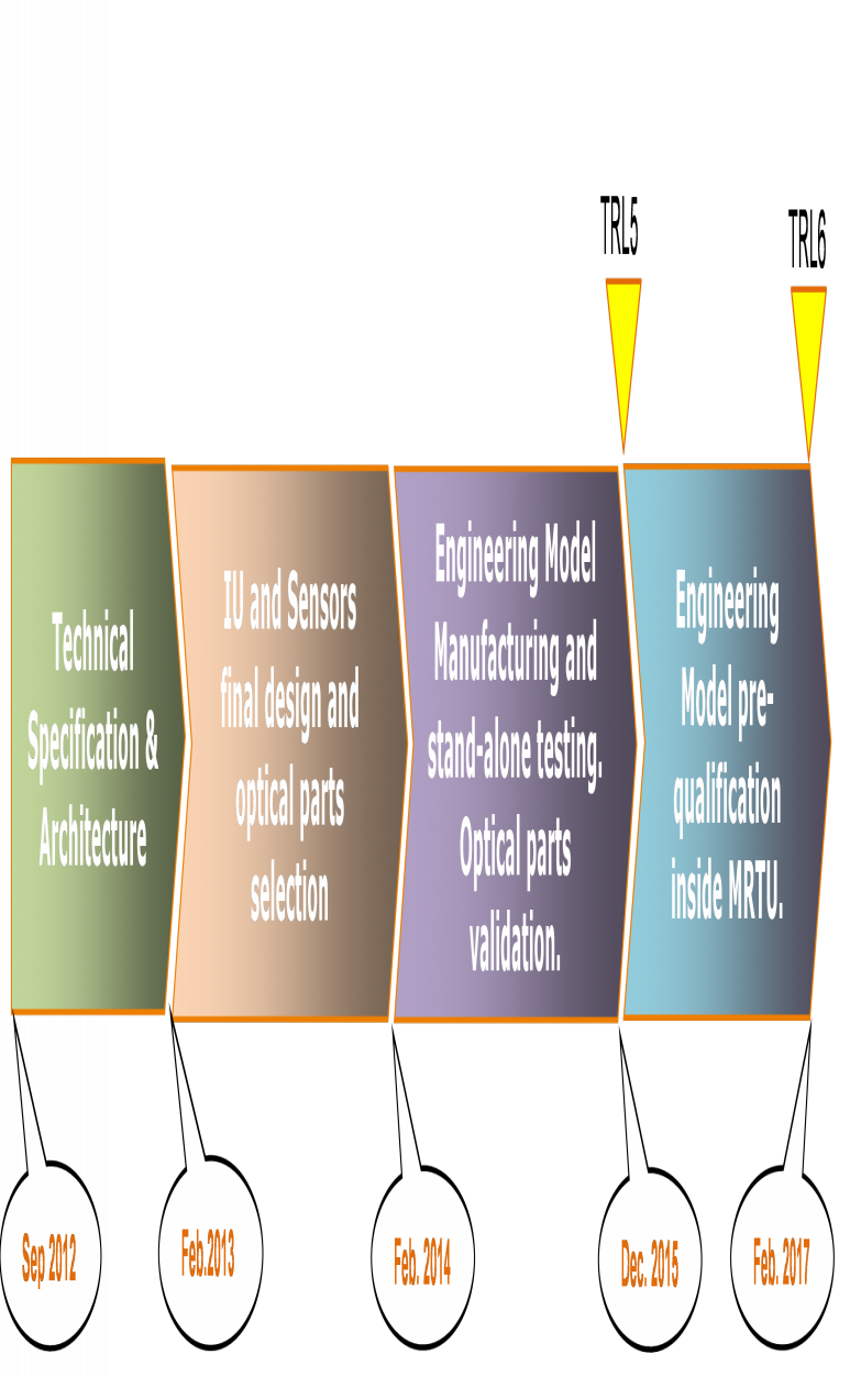
The project has been completed
TRL5 reached for FOS Technology
- FOS Interrogation Unit designed and manufactured according to space standards
- FBG sensors design, manufactured and validated for space
- Integration of the acquisition algorithm in a space FPGA
- Optical parts selection and pre-validation for space applications
- EM FOS performances characterized in stand-alone configuration
- Functionality and performance inside a Modular RTU validated
- EM FOS characterized in thermal environment at qualification levels.