-
StatusCompleted
-
Status date2017-06-23
-
Activity Code7A.029
The main objective of the project was the design, bread-boarding and testing of a dual independent beam Ka-band terminal for MEO satellites.
Currently the usual solutions for this application are based in two separated ground stations. Obviously, having two different ground stations, two independent beams are able to be generated and therefore two satellites can be tracked simultaneously and deal with the handover process.
The challenge of this new development was to have a single ground station antenna able to generate those two independent beams simultaneously. This way, the new terminal goal was related to an improvement in size and simplicity of the antenna installation without increasing the cost significantly.
Based on the radar technology, TTI proposed a dual beam system composed by a single and static reflector and two feeders that move along x, y and z axis being able to simultaneously track two satellites and provide the handover process capability.
To do it, a requirements assessment was carried out defining a scan range of 40º based on a scenario of 16 satellites.
The main challenge of the project was to design, implement and validate a ground terminal able to produce two beams simultaneously using a single reflector.
When Independent Tracking Dual Beam Antenna system is compared to the actual solutions, it needs to be smaller, lighter and price competitive; and consequently the project become highly challenging.
Another important challenge was to be able to design a terminal in which the scan range can be upgraded easily. The same design needs to be valid for 9 or 16 satellite constellations.
Main benefits of the system is the reduction of size, weight and complexity in the installation by using one single static reflector and mobile feeders instead of two full ground stations.
While actual MEO ground stations are composed by two reflectors and consequently, two mechanical systems, two feeding system and two motorization system, ITDB antenna has a single static reflector; and for this reason, it is smaller, lighter and easier to install.
ITBD antenna is an scalable system, which mechanical system is compatible for 1.2m, 2.4m and 3.6m reflector. In addition, in case needed the presented solution can be upgraded to increase the scan range by adding another reflecting surface, but not adding more motorization or feeders, just by using one mobile reflector at each one.
Next picture shows the design of the 1.2m diameter breadboard.
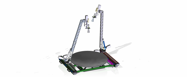
Figure 1. ITDB Antenna 1.2m breadboard
Independent Tracking Dual Beam Antenna is composed by a single fixed reflector and two tracking feeders. ITDB antenna presents the ability to track two simultaneous MEO satellites allowing the handover process. ITDB antenna is designed for a 16 satellite constellation providing a +/- 20º scan range; nevertheless, a chamfered version is analyzed in order to increase the scan range to +/- 40º. The ITDB antenna total weight has been reduced significantly when comparing with the actual solution.
In addition, it is important to remark that ITDB antenna substitutes two complete tracking ground stations by one single installation.
Consequently, the optimization in cost, footprint and weight are the main goals of this development.
The following figures illustrates the bread-boarding developed at TTI's anechoic chamber and the obtained measurements.
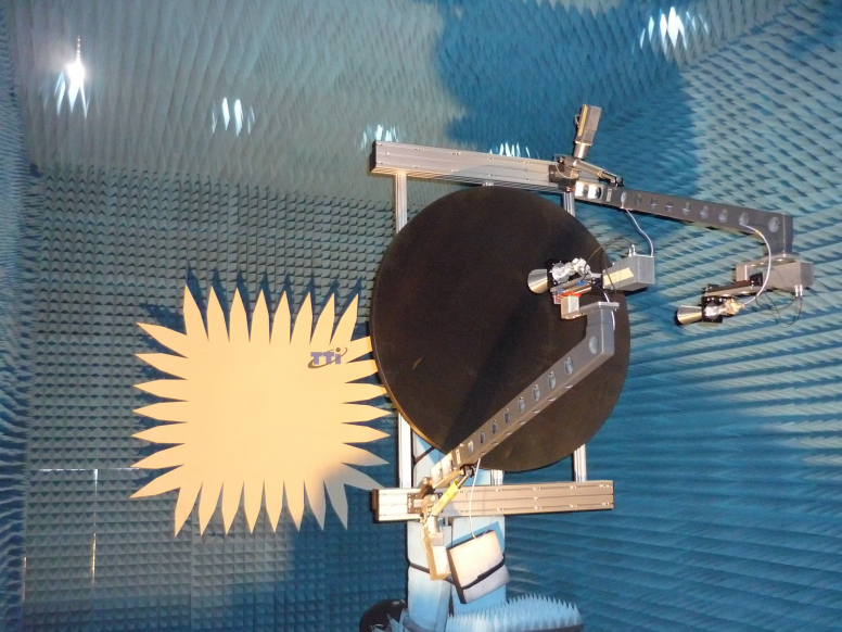
Figure 2. ITDB Antenna breadboard in anechoic chamber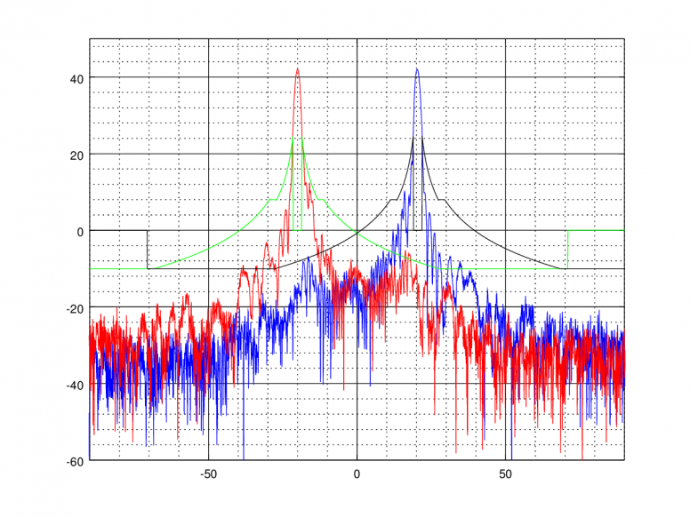
Figure 3. ITDB Antenna breadboard measurement. Both beams activated simultaneously for handover purposes. Blue scanning at 20º and red scanning at -20º. Green and black curves represent both mask compliance regulation. The plot represent Gain (in dB) vs angle (in degrees).
The picture shows the measurements of two beams generated simultaneously. The measurement was made at 28 GHz and shows a blue circular polarized pattern pointing at 20º and a red circular polarized pattern pointing at -20º. Both patterns were compliant with a gain > 42 dB, XPD > 20 dB and fulfilling side-lobe mask requirements (FCC 47 CRF 25.209)
The system is composed by two feeding corrugated horn antennas and a single non-offset reflector.
The mechanical and motorization subsystems provide a precise and accurate values for each axis movement.
The system provides continuous tracking of two MEO satellites by handling the satellite handover through following phases:
- Home-Process: Initialization process. Both feeders locate at their start position.
- Pre-tracking Process: One feeder is set as ready and the other one hide just for not disturbing the main one. This phase involves move the elevation axis from the home position to the one in the middle of the reflector. This process takes about 5 minutes. At this moment the system is ready to track a satellite
- Tracking Process: During this phase one feeder stops to not disturb the active one. On the other hand the active feeder moves in the three axis to track the satellite.
- Recovering Process: When the active feeder is at 75% of the X axis, the hidden feeder moves to the front position. Once it reaches the X initial position it begins to move elevation axis to place the feeder in the middle of the reflector. At this time it is ready to catch the next satellite
The following figure shows the state-machine diagram:
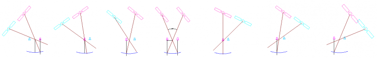
Figure 4. ITDB Antenna system state machine diagram
Dual Beam project has been implemented in three different stages. First, the desired requirements have been evaluated and a pre-design is developed. Every requirement is obtained trying to duplicate the same characteristics as dual ground stations, composed by two antennas, with the unique limit of the scan range of the system. After the design, a complete prototype was implemented, manufactured and tested in order to validate the system. From this point, some upgrades have been identified and an industrialization phase and field tests should be carried out.
Project completed.
The project has been closed successfully and as output not only a design but a prototype has been implemented, manufactured, tested and validated. The obtained results have successfully achieved the project goal meeting all the requirements. After considering the results and the manufacture process different improvements are considered for future product design.