-
StatusCompleted
-
Status date2023-01-23
-
Activity Code5C.282
The main object of this Atlas program was to manufacture, perform PFM testing and deliver flight models to the Columbus Ka-band Terminal. The total delivery (including FMs) consisted in prime and redundant frequency up-converter units and prime and redundant down-converter units between Ka-band and L-band.
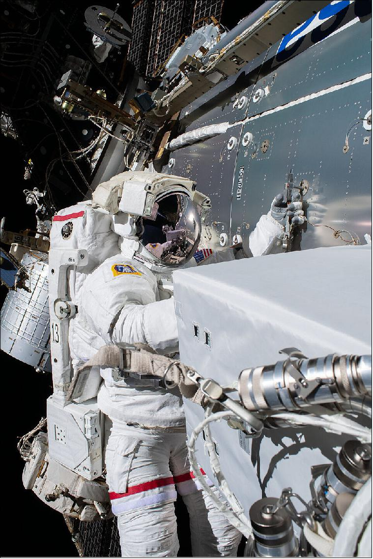
The product developed is in general targeted to meet the Ka-band ISL market and Kongsberg have been a part of the MDA team developing this product. The first flight opportunity was the ColKa, a Ka-Band terminal to communicate from ISS Columbus to EDRS.

The frequency converters between Ka-band and L-band are tailored to meet the requirements of generic Inter Satellite Link terminals, typical for LEO-to-GEO communication. Normally these converters will have a fairly narrow receive section and a broadband transmit section.
Both the converter units are challenging. A common challenge is the relatively high input or output frequency. Ka-band designs will always give challenges in implementation. For the Up Converter, it is difficult to maintain a flat in-band response and the required group delay flatness over the defined 400MHz bandwidth. For the Down Converter, the Ka-band input frequency and a relatively high gain result in challenging test methodology to assure accuracy and repeatability in the tests.
The frequency converter units are designed to fit onto a customer specific architecture for converting from Ka- to L-band and vice versa. However, the design will give the basis for a generic design fitting in future Ka-band Inter Satellite Link terminals. Furthermore, the Ka-band technologies can be further developed in other product lines at KSE.
For the Down Converter, the Ka-band input frequency is converted in a single converter stage down to an L-band frequency. This includes filtering and amplification of the received signal.
The Up Converter Unit provides the frequency translation from L-band input to Ka-band. This is also performed in a single conversion stage. The unit also provides the required filtering and amplification. The BW for the upconverted signal is 400MHz.
Both the Down Converter and Up Converter units includes internal frequency sources for the frequency translation as well as internal DC-DC converters.
Down Converter Chain Description:
The incoming RF signal at Ka-band is routed through a waveguide isolator followed by a Ka- to L-band converter hybrid. The converter hybrid contains a single mixer stage for frequency conversion together with filtering and amplification of the RF signal. A Temperature Gain Control (TGC) to ensure a stable performance over temperature.
Up Converter Chain Description
The incoming RF signal at L-band is routed through the L-band PCB, which utilizes filtering amplification and Temperature Gain Control of the signal. A converter hybrid is located after the L-band PCB and contains a single mixer stage for frequency conversion from L-band to Ka-band. From the converter hybrid, the signal is routed through a waveguide filter to suppress unwanted mixing products and the LO leakage, and into a driver hybrid to provide the required output level.
LO Generation (similar for both units)
The reference signal for the LO frequency synthesizer is generated by an OCXO. A sampling phase base synthesizer is generating a LO signal at L-band, which is multiplied by a factor of 18 in three separate multiplication stages to reach the desired Ka-band frequency.
EPC (similar for both units)
The EPC is realized by a fly-back converter topology and transforms the main bus voltage of +28V nominal to the required secondary voltages.
The Project Plan consists of the following milestones
-
Contract Kick Off
-
PFM Test Readiness Review
-
PFM Acceptance Review
-
Commissioning Results Review
-
One-Year-in-Orbit Results Review
-
Final Review
Completed.


