-
StatusCompleted
-
Status date2023-07-10
-
Activity Code4E.072.
The objective of the activity is to design, develop, manufacture and test a high-resolution magnetic brake solution to increase the unpowered holding torque of rotary actuators used in mechanisms for telecoms applications (e.g. appendage deployment and positioning).
The main specifications given by ESA are:
-
Minimum 200 stable braking positions
-
Targeted holding torque: 120mNm
-
No tribological layers. No generation of debris
-
Inner diameter: 35mm
-
Length: 15mm
-
Outer diameter: 55mm
-
Mass lower 150g
-
Operating qualification temperature: -45°C - +100°C
-
Mechanical override without damage
-
Fully redundant power lines
-
Minimum power consumption
-
In-orbit life duration of minimum 15 years
-
ITAR free
The main challenges are:
-
Common „magnetic brakes“ use tribological layers as brake. Only actuation is done electromagnetically.
-
Eddy current brakes do only provide holding torque while movement (e.g. rotation of axis).
-
Hysteresis brakes provide even holding torque without movement but tend to have stepping even in released mode (ripple)
-
Active) reluctance brakes are not commonly available and rare information on products / prototypes is found.
A completely new technology has to be invented.
The magnetic brake provides up to 176mNm holding torque at a size to fit the SAGEM21PP in environment from air to vacuum and from -45°C up to +100°C. The brake’s state is toggled between release / brake with an electric impulse of 21V, 7.8A and 10ms - no special electronics is needed. The design is easily adaptable to customer needs to fit other actuators with a different size or different number of stable positions. The magnetic brake has no tribological layer - no generation of debris. In case of faulty operation, the motor can actively override it without damage. The costs for a magnetic brake as commonly available serial product (ITAR free) are estimated to be clearly below 10k€.
The magnetic brake enables the usage of smaller actuators and / or safe energy by switching off the actuator and use the magnetic brake to provide the necessary holding torque (instead of the powered actuator). No comparable competitor products are available.
The magnetic brake is fully compliant to the specifications given by ESA and potential customers:
-
Size (fits to SAGEM21PP):
-
Inner diameter: 13mm
-
Outer diameter: 51mm
-
Length: 10mm
-
-
Holding torque: 0.176Nm
-
200 stable positions
-
No permanent power for locked or released state necessary
-
Minimum switching power: 164 W; min. switching energy: 1,65 Ws (21V /7.8A / 10ms)
-
Voltage level: 20-32V (lower voltage leads to lower holding torque / no fully release)
-
Fully redundant design
-
Total mass: 150g
-
No tribological layer – no generation of debris
-
Mechanical override without damage possible
-
Tested on shaker without damage
-
Operational temperature range: -45°C to +100°C
-
ITAR free
-
Compliant to ECSS-Q-ST-70-02
-
Endless rotation / no speed limitation
-
No complex electronics necessary
-
Can be easily adapted to fit other actuators
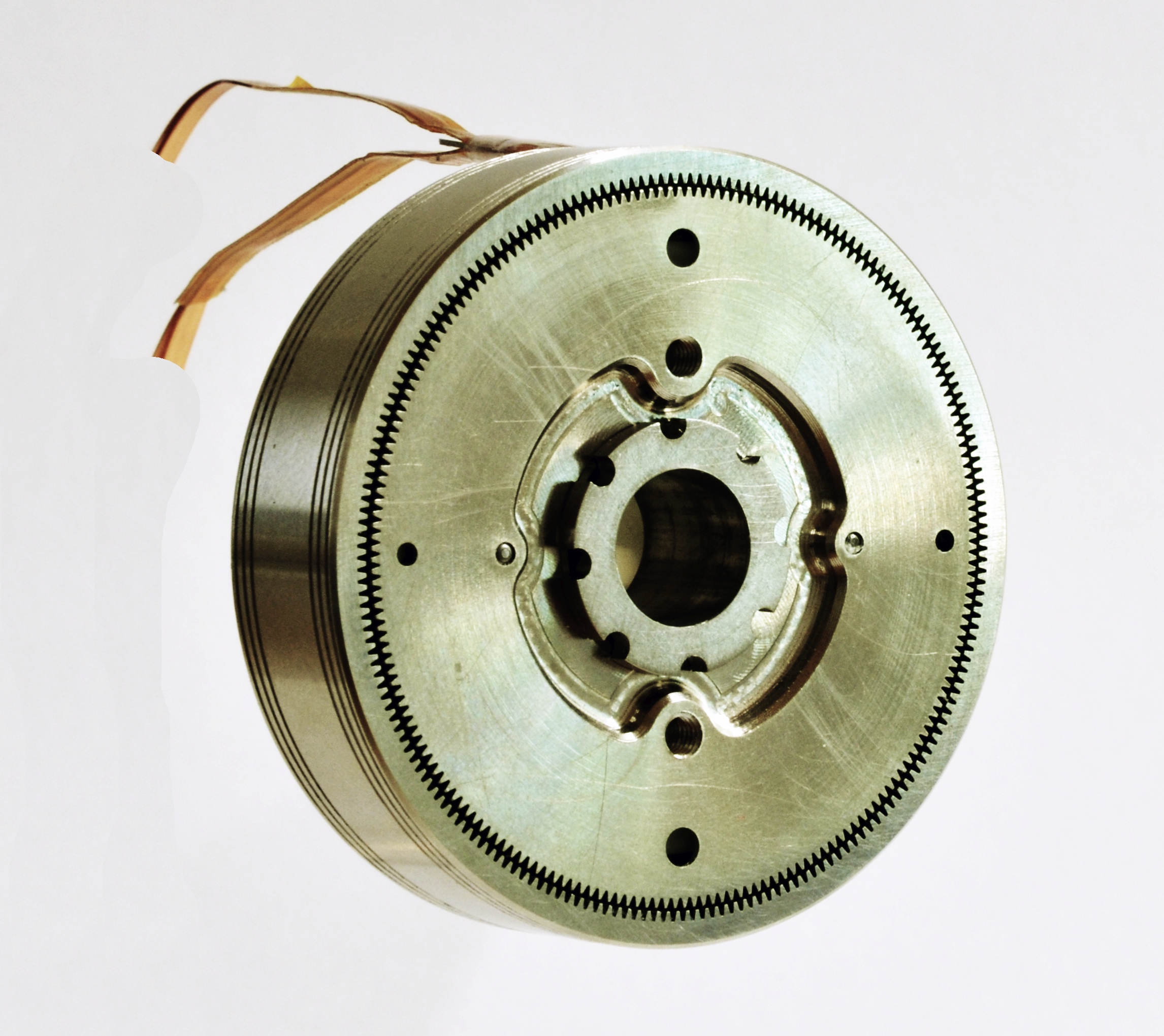
The magnetic brake consists of stator and rotor, which need to be integrated onto the customers actuator stator and rotor. The axis of the customers actuator has to take up the rotor of the magnetic brake. Additional adjustment tools to align the magnetic brake to the customers actuator are available – especially for synchronization of magnetic brake with a stepper motor.
All parts of the magnetic brake Engineering Model are already produced in close-to-production techniques to proof high quality and still meet the harsh cost criteria of potential end-users. Actuation is done without complex electronics, only an electric pulse is needed to toggle the brake’s state.
The project is processed in 7 steps:
-
Review of State-of-the-Art and Application Survey
-
Finalised Technical Requirements and Selection of Baseline Solution – Milestone: Specification Review
-
Magnetic brake Breadboard version: design and hardware – Miilestone: Preliminary Design Review
-
Breadboard performance characterisation
-
Magnetic brake Engineering Model design and adaptation of baseline actuator – Milestone: Design Review
-
Engineering Model and full assembly (with actuator) performance characterisation
-
Overall Evaluation – Milestone: Final Report
The project has been completed. Magnetic Brake Breadboard Model and Engineering Model are designed, built and tested. The Engineering Model is fully compliant to the specifications of ESA and the input of potential customers are considered as well – especially the cost requirements for a serial product could be met as well.