-
StatusOngoing
-
Status date2019-01-17
To realize missions with multi-spots, linguistic or shaped coverage, it’s necessary to develop compact feed networks with performances in accordance with the specifications. Feed networks have been used extensively in recent years to achieve this type of mission in Ka frequency band. Feed networks had, for these frequency bands, a dimension and mass relatively low despite the high complexity of it. Indeed, the majority of these networks have been realized in waveguide technology thanks to these small dimensions. In contrast, if the same type of mission will be carried out for frequency bands from L-band to C-band, waveguide technology does not seem the most appropriate technology to achieve a compact feed network. The mass and dimensions of the equipment will then become too important to be onboard into a satellite. it is necessary to evaluate different technologies which could allow a feed network product with acceptable mass and dimensions.
As the wavelengths are very large at these frequency bands, an important challenge is to reduce significantly the weight and size of the multibeam/multifeed network (especially beam forming network) in order to allow the accommodation at satellite level. This must be achieved with good RF performances.
In addition, one of the most important points is the capability to scale the developments carried out in a frequency band to another to be as generic as possible. The selected technology is demonstrated over a “wide” frequency band to answer efficiently to a large number of applications.
It will also ensure that this technology can easily be industrialized.
In addition, the product should be developed without procurement restrictions.
The most difficult to achieve for a feed network is to integrate N*M RF paths (N is the number of beam and M the number of radiating element).
The expected main benefits with the selected technology (to realize beam forming Network from L to C band) are :
- Capability to address large feed arrays (a lot of inputs and outputs)
- No procurement restrictions
- To be as generic as possible
- To easily be industrialized
- Large fractional bandwidth
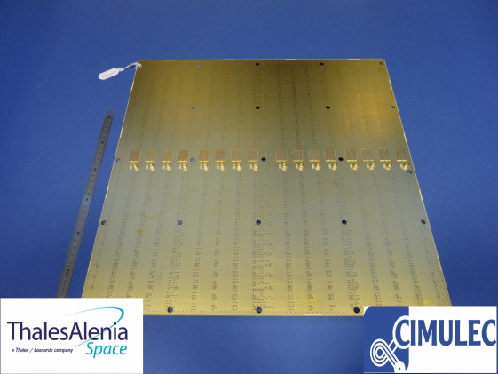
A divide/combine breadboard of the BFN has been manufactured with a great improvement of the European “state of the art” :
- 1200 elementary components
- 16 inputs and 26 outputs
- To realize larger boards (435 mm²) with 4 RF levels (9 coppers)
- To realize large feed array by stacking boards (see figure) and compensate discrepancies due to dielectric dispersion between materials by using “phase correctors”
- Implement a new connector on order to have a better shielding
- Increase fractional bandwidth with compact phase shifter (up to 6-8 %)

The receive antenna of the base solution is a full active antenna that generates 16 beams with 52 radiating elements. A view of the active antenna functional block diagram is following figure. It is composed of
- 52 radiating elements
- 52 LNA/filter
- 1 Beam Forming Network 16x52
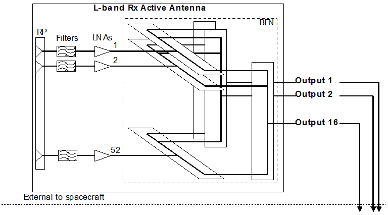
The chosen BFN for this antenna is a “parallel” BFN. This BFN is constructed by stacking several two-dimensional elementary BFN as shown in following figure.

This BFN architecture solution use only 3 dB hybrid power dividers and thus could provide low dispersion beamforming performances.
This study will be divided in 8 tasks :
- The first and second task will be ended by the SRR. The main activities to be done are a “large state of the art” review including technical solutions and associated technologies for very compact feed network. This review will be performed in phase with the consolidation of the mission scenario and associated antenna and feed network requirements.
- The third and fourth task will be dedicated to Preliminary design of the feed network baseline and back-up. A consolidation of the design and technology trade-offs considering the mission scenario and antenna configuration selected in the previous task will be done.
- The fifth task is the detail design and EM definition.
- In the sixth task, The EM will be manufactured. Measurement will be performed in seventh task. As a concluding task (task 8), A review of the achievement of this activity will be done.
The work as defined in the original contract is completed. The RF test were successful and it was demonstrated that phase discrepancies between two identical boards after manufacturing may be corrected using small “add-ins” components named “phase correctors”. Input and output return losses were a little worse than expected and the root cause of the problem remains unexplained despite a large number of investigations. A CCN is being defined to better understand and eventually solve this issue. Otherwise, all other performances (electrical and mechanical) are in accordance with the product specification. Considering the technical improvements included in this Engineering Model (number of RF paths, phase correctors, bandwidth, …) and the complexity of the product, these first results on ARTES 5.1 contract are very promising.