-
StatusCompleted
-
Status date2020-12-16
-
Activity Code5C.200
In satellite communication new frequency bands are being used to handle more and faster communication. For RUAG Space AB to remain a leading independent supplier of converters and receivers, being able to deliver space qualified converters operating above Ka-band is essential.
The Ka/Q-Band Up Converter Programme objective is to complement and further strengthen RSE’s converter and receiver products by performing following key development activities in the Q/V Converter product area:
- The design and development of a Ka to Q Upconverter, realized as an EM hybrid.
- The design and development of converter mixer and PA MMICs.
The design must also weigh in evaluations of manufacturing costs when making initial trade-offs.
Manufacturing products for RF signals at very high frequencies drives the requirement for high manufacturing control and accuracy, one area where this is extra challenging is the Q-band WG interface.
Accuracy and attention to details must be fulfilled at the same time as the product needs to be competitive cost wise.
MMIC Design in Q-band (40 GHz) is challenging and will require careful modelling and optimization. Spurious signals suppression, is challenging, and requires use of advanced mixer topologies.
The program will make RUAG Space competitive both in Europe and US in the product area.
A small, light-weight hybrid with possibility to use solderless contacts suitable for industrial assembly.
The use of deep access bonding makes use narrow cavities possible and integrated MMIC design reduces the number of interfaces.
Excellent filtering performance with an external filtering solution that can be adapter to an specific frequency plan.
The Converter RF chain comprises four main components:
- Input filter
- Mixer MMIC including buffer amplifiers
- Output filter
- Output amplifier MMIC
The nominal gain of mixer MMIC and output amplifier MMIC is based on a converter unit gain of typically 30 dB. The sum of the mixer and output amplifier MMICs nominal gain values gives 10 dB margin for filter and other losses/ tolerances.
A block diagram is given below.

|
BDR |
July 2016 |
|
PDR |
Sep 2016 |
|
Delta BDR/PDR |
Nov 2017 |
|
Phase 1 Review |
Nov 2019 |
|
TRR |
Sep 2020 |
|
Final Review |
Dec 2020 |
A Ka/Q-Band Up Converter EM hybrid with MMIC mixer and output amplifier has been designed, manufactured and tested.
The development has included a novel, and also challenging, approach with respect to miniaturization and integration of high frequency functions (+40 GHz). Several new steps, and not always obvious, have been achieved with very promising and encouraging results.
The achieved results have been very successful, and the next step is to develop a fully functional and integrated EQM, including the necessary power supply and LO generator.
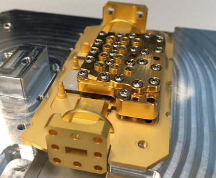
Picture of hybrid with mounted filter.
The Project is completed.