
-
StatusCompleted
-
Status date2022-12-05
-
Activity Code5C.326
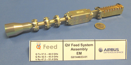
The objective of this project is to design, build and test a Q/V-band Feed System EQM (Engineering Qualification Model) so that this technology is qualified for flight use on future GEO VHTS systems.
This project draws on the successful development of a Feed System EM (Engineering Model) through a previous ARTES 5.2 programme.
The Feed System EM is shown in Figure 1.
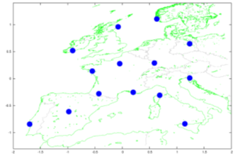
This product’s primary use is for gateway feed chains in multi-spot beam antennas on board geostationary VHTS systems. The usage of the Q/V-band on the gateway link frees up spectrum on the Ka-band user links. With the exception of the mission specific filters and feed horns, these feeds are generic and can be adapted for different missions. An example Q/V-band gateway coverage is shown in Figure 2.
The Q/V-band Feed System has to be a slim-line design:
-
compatible with up to 7 feeds and 30mm spacing between feeds with suitable mechanical interfaces in a feed cluster.
-
covering the complete Q Tx, Q Rx and V Rx bands
-
operating in dual circular polarisation over all frequency bands
-
capable of handling maximum RF power levels without risk of multipaction
-
exhibiting low PIM performance over temperature
-
compatible with the envisaged thermal and vibration environment at component level as well as Feed System level
-
achieving required RF performance across multiple builds
This feed product extends telecom satellite capacity by using Q/V-band for gateway links and maximising the Ka band spectrum for broadband telecommunications (up to 1 Terabit/s).
This Feed System is capable of operating with any frequency plan over the Q/V-band in very tightly spaced feed cluster environments.
The Q/V-band Feed System provides both RHCP & LHCP functions in the transmit and receive bands, with an axial ratio requirement below 0.49dB. (XPD >31dB). Feeds can be spaced as close as 30mm apart.
The core polarisation network is generic and covers the full Q/V-band frequency plan. Only the filters and the horns may need to change between missions. Because of the modular design approach, maximum flexibility is achieved with minimal project specific adaptation required.
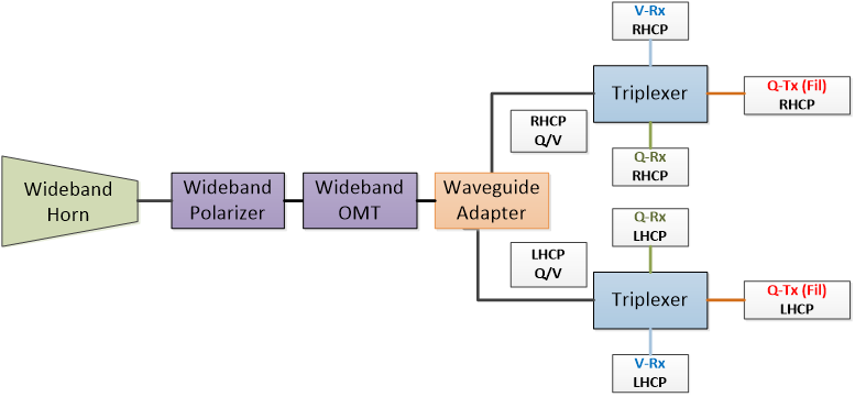
A generic wideband feed architecture has been selected for this EQM feed development. This comprises of a wideband feed horn, wide band polariser, wide band OMT, and a pair of triplexers to accommodate the most challenging filter frequency plan, as shown in Figure 3.
Phase 1: KO to PDR
Preliminary design phase includes activities to validate key technologies used in EQM. PIM test requirements are defined.
Phase 2: PDR to CDR
Detailed design and analyses performed. Plans defined for PIM tests.
Phase 3: CDR to TRR
EQM components are manufactured. Components and sub-assemblies undergo RF health checks before full Feed System is assembled and RF tested.
Phase 4: Final Review
Feed System EQM is subjected to qualification testing (thermal cycling, vibration, power handling and PIM tests). Test reports are included in FR documentation.
Phase 4 completed.
Flight qualification of the Q/V-band Feed System is complete.