-
StatusOngoing
-
Status date2017-02-24
-
Activity Code1B.076
The RAMSES project has been defined with the following key objectives:
- Identify configurations of interest and define associated reference scenarios through analysis of the trends and evolutions in the MSS domain (advances in the regulatory framework, evolution of the market: user demand, types of applications, market segments)
- Perform a review of state of the art technologies based on current roadmaps (institutional and industrial plans or commercial initiatives) and extrapolate the available technologies in the 2025 timeframe covering aspects related to satellite platforms, launchers, satellite antenna and repeater technologies, air interface, terminal and ground infrastructure
- Evaluate the adequacy of the currently foreseen MSS architectures (benchmark design) in front of the future needs in 2025
- Elaborate advanced designs (targeting breakthrough technologies) to overcome the performances limitations of the benchmark designs
- Define a well-structured roadmap for the European and Canadian Industry, in order to identify potential gaps in the current roadmaps as well as to secure the successful deployment of Next Generation MSS in 2025.
From a technical point of view, the key challenges are in capabilities to have a flexible satellite network for MSS operators allowing reconfiguration of the system depending on user needs and operator constraints (satellite relocation, backward compatibility, ramp-up strategy, traffic profile).
Another critical aspect is to have global coverage and increase system capacity w.r.t. existing MSS systems.
The overall objective of the RAMSES project is to define candidate satellite architectures answering MSS operators’ needs and vision, with backward compatibility. These satellite systems are designed for smooth satellite replacement.
Nowadays, end-users are always more mobile (on a global scale) and ultra-connected to their networks (professional and personal). To meet these requirements, as well as to maintain their systems profitable, the
MSS operators tend to broaden their range of offered MSS products, in a growing number of markets (aero, maritime, land-mobile) and for various services (narrowband voice and data, broadband, low data rate solutions, machine-to-machine).
In the frame of RAMSES several satellite system configurations have been defined to answer to MSS operators needs for next-gen MSS:
- LEO satellite system for M2M applications
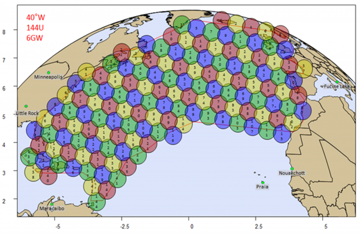
- Benchmark GEO satellite system in Ka-band to increase satellite coverage over Atlantic Ocean
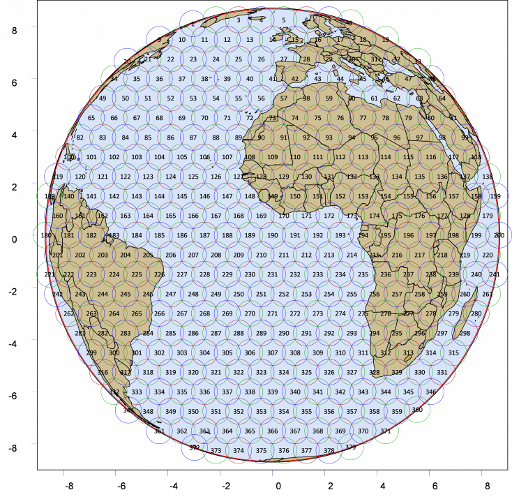
- Advanced GEO satellite system in Ka-band to replace existing Inmarsat satellite (2025) with global coverage– 2 configurations have been analysed.
The RAMSES system provides two-way high data rate communications between mobile users, located anywhere on the Earth visible to a GEO satellite, and the world’s terrestrial communications networks. Land, sea and aeronautical users are served.
Configuration #1
The feeder link antenna system consists of 6 SFPB steered reflectors of diameter 0.85 m. The global coverage antenna system uses separate Ka-band horns for both transmit and receive. The switching system that drives the beam-hopping capability is intended to be integrated onto the back of the feed arrays. This system will use fast switching ferrites so avoiding the problem of mechanical wear.

The payload can be considered to consist of various sub-payloads. The global payload with 448 narrow spot beams over the face of the visible Earth can be conveniently broken into the following parts.

Configuration #2
The high capacity payload antenna system is identical to Configuration 1 except perhaps in some minor ways concerned with the mounting to the platform. Similarly for the feeder link antennas.

The payload can be considered to consist of various sub-payloads just like Configuration #1. Many features are the same as the previous configuration.
Differences from Configuration 1 include:
- The global payload receive and transmit integrated DRAs
- A different number of RF paths between the DRAs and the processor
- Different nature of the connection between DRA units and processor (optical)
- Different sized commercial DSP with beam-forming function.
The global payload RF paths within the integrated DRA units are phased aligned, then between DRAs and main DSP the paths are optical digital and need to be time aligned.
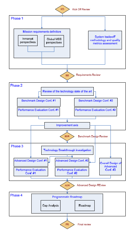
The RAMSES project has completed the steps of :
- clarifying the requirements to be met,
- defining Benchmark System designs and assessing their performances
- identifying breakthrough technologies for Advanced Systems
- defining Advanced Systems and assessing their performances
perform gap analysis and define programmatic roadmap
Phases 1/2/3/4 have been finalized (Final Review in May 2016).