
-
StatusCompleted
-
Status date2020-01-08
-
Activity Code4E.066
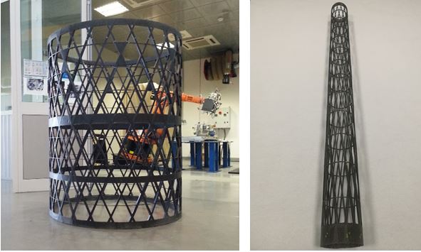
The overall objective of the project is the development of design and manufacturing methods for the realization of highly efficient tubular CFRP grid structures for space application and most in general to demonstrate that the grid architectures can be applied to the proposed two breadboards: 1) Boom segments for a deployable antenna and 2) Central Tube for satellite support.
The overall objective has been led through the achievement of three specific goals:
- development of an optimization methodology for grid structures based on analytical and numerical methods.
- development of the automated manufacturing process
- design of different types of mechanical interfaces to other structures and elements (i.e. to a ring interface, and for inserts)
- validation of the developed methods through local and global tests
CFRP Grid Central Tube:
- Payload Mass: 4500 kg
- MAX Limit Flux: 250 N/mm
- Global Stiffness Properties:
- 0.0180 mm (+/-20%) under 10 kN in axial direction
- 0.20 mm (+/- 20%) under 10 kN in lateral direction
- Weight saving: 20% (reference monolithic composite structure)
CFRP Boom:
- Mass per unit length: 0.5 kg/m
- First Natural Frequency (bending) with 60 kg at the tip, 3.0 m long:1.5 Hz
- Thermal conditions and stability (Max. longitudinal gradient = 18°C/m; Max. radial gradient = 333°C/m; Negative CTE): Maximum tip displacement = 0.15 mm
- Baseline Material: High Modulus carbon tow
- working temperature: ± 160°C
Starting from the assessment of the structural and functional requirement of both demonstrators, the advantages of the Grid solution with respect to potential existing competitor systems are:
CFRP Grid Central Tube (ref CFRP sandwich solution with High Modulus Fiber):
- Weight saving: 20%
- Open structure: accessibility to the inner volume (easer installation of equipment, adjacent or secondary structures, harness, or the integration of attachment points)
- Integrated composite flanges (intermediate and external flanges)
- Local composite reinforcements for attachment points
CFRP Grid Boom (ref. monolithic solution):
- Mass per unit length: 0.5 kg/m
- Higher stiffness to weight ratio
- Open structure: accessibility to the inner volume
- Lower thermal gradients (thermal stability behaviour w.r.t. radial and longitudinal gradients)
- Lower CTE of the Ribs
The Design and Manufacturing approach demonstrated during this project allowed us to assess the outstanding weight efficiency, versatility, and general performance of CFRP grid structures (without the skin) based on Parallel Filament Winding of dry fibers and resin infusion.
Indeed, the design requirements were very challenging for both the applications, CT and Boom.
This manufacturing approach, combined with high modulus fibers, guarantees the required stiffness and strength, both globally and locally, and a regular and homogeneous dimension of ribs which facilitates the equipment installation. This fact is not taken for granted on analogous applications based on the use of prepreg materials, where distortion of ribs is typical. In addition, the proposed process is highly efficient and cost-effective, since there is no need of autoclave (a simple oven is sufficient) nor sophisticated deposition equipment, but still maintaining the capability to integrate locally tailored reinforcements.
Considering the two CFRP grid demonstrators as subsystems of a more complex system, they shall ensure the transfer of the loads and guarantee the specific functionalities to the space system in which it is integrated.
The Central Tube must interface with the launcher and earth deck, through external metallic flanges and with shear wall, has to provide several local attachment points for intermediate deck, shear web, and fuel tank connections.
For this reason, the diameter of the demonstrator is the nominal one (1194mm) in order to interface the launcher, while the length is smaller than the reference (1500 mm vs 2700mm).
Moreover, the structure has composite integrated flanges and several local carbon reinforcement area interlaced with the grid to provide robust interfaces for substructures:
- 2 external composite flanges to connect to the launcher and earth deck
- 1 intermediate composite flange for the intermediate deck
- several local attachment points for shear web and fuel tank
The Boom demonstrator is a segment of 1500mm (vs 3000mm of the reference) and the nominal diameter of 120mm. In order to interface with hinges for deployment and twisting mechanisms and with other metallic interfaces it has two end rings carbon fiber integrated flanges.
Assessment of requirements;
Milestone 1: RR
Preliminary Design
Development of Design and automated manufacturing methods (based on CIRA Grid Technology experience) for a Central Tube and Boom grid benchmarks
Manufacturing of two grid Technological Models to extract samples and sub element to be tested
Milestone 2: PDR
Critical Design
Implementation of the Critical Design and definition of the global test.
Milestone 3 and 4: CDR, MRR
MAIT
Manufacturing and the testing of two final Grid Benchmarks for global tests
Milestone 5 and 6: TRR, TRB
Results
Correlation and comparisons of results of grid solutions with respect to reference
Milestone 7:FR
The project has been completed.
The Design and Manufacturing approach based on Parallel Filament Winding of dry fibers, resin Infusion and OoA curing, demonstrated the outstanding weight efficiency, versatility, and general performance of CFRP grid structures (without the skin).
The predictions of design and analysis was very good, confirming the effectiveness of the methods.
The maximum total flux in compression of the Central Tube was very high (1.86 LL) at compression failure, with a weight saving near 20%.
Also the Boom Demonstrator has fulfilled the challenging design requirements in terms of mass, stiffness and CTE (very low and negative)