-
StatusCompleted
-
Status date2020-09-21
-
Activity Code4B.148
The objective of the project is to perform phase B (until PDR) of the TDTM development. TDTM will be designed to answer Space Inspire new generation platform requirements. The objective of this early phase is to identify technical risks relative to the technical proposed solution and launch all necessary derisking activities.
The objective is to propose at the end of the project the highest TRL and a set of analysis supporting the design.
Development of one generic product compatible with 2 different GIE thrusters (T6 & RIT2X), avoiding penalties on technical/design choices and keeping final competitiveness of the product.
Beyond the large technical differences between both thrusters (electrical, fluidic, size), the other main technical challenge concerns the selection then qualification of a high voltage harness (wiring & connector) submitted to very high constraints (2KV operating voltage, large number of thermal cycles, large cumulative ON time, high temperature, large number of cycles).
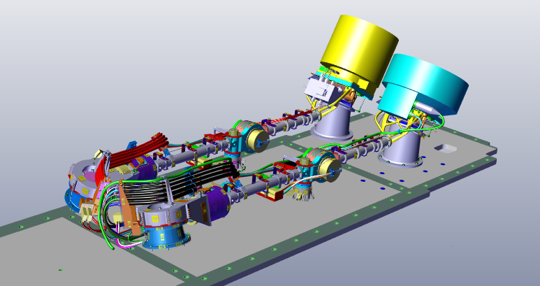
The TDTM offers the capacity of a 1,5m deployable 90° from stowed position arm providing once deployed additional 3 axis +/-35° angular orientation for an enhanced torque control capacity and pointing range, which, associated with the high thrust efficiency of the GIE thrusters, will boost propulsion subsystem efficiency.
The objective is to have at production level a generic product whatever the North or South accommodation on the spacecraft, and whatever the final thruster mounted (electrical and fluidic lines termination left on responsibility of thruster integrator). Total TDTM mass (without engine) will be below the 25Kg specification.
Developed for new Space Inspire platform, North and South TDTM compactness is a plus. Both TDTM only require a reduced implantation area. In addition, TDTM compactness allows N+S TDTM stowed configuration requiring a limited volume, in line with Space Inspire launch configuration where the available volume is limited.
The 95% generic solution for North & South TDTM whatever the final thruster, rely on:
- A simple, light, cost competitive mechanical full aluminium architecture.
- Qualified, accurate, robust, and well known SARA21 rotary actuators.
- Qualified, low shock nut for LLD solutions.
Electrical: GIE harness relies on COTS Axon cables that fulfils need for high voltage insulation, high temperature resistance, high radiation resistance, while keeping an acceptable flexibility, volume and mass. Despite important electrical differences between both thrusters, harness definition (wires and connectors) is generic. Protection of the harness on flexible area is ensured by stainless steel flexible hose (ETHM heritage) which offer at the same time,
- good radiation, and strong micrometeoroid protection,
- the routing of the bundles while leaving the cables free which allows the limitation of the resistive torque,
- separation of the different bundles limiting EMI,
- electrical conductivity ensuring easy continuity with EMC insulation of fixed sections,
- a good radiative exchange with space for dissipative cables thermal control,
- cheap industrial solution,
- while remaining very flexible with intrinsic very low resistive torque
Fluidic: Robust, simple, and compact technical solution for the 3 hinges relies on hardened stainless steel pipe (high yield limit). +/-120° and +/-35° spire capacity for respectively axis 1 and axis 2. Simple straight pipe for +/-35° axis 3.
The TDTM mechanical architecture is a quasi-100% aluminium machined parts offering a good assembly accuracy. Its movements are ensured by 3 flight proven reliable SARA21 rotary actuators.
Fluidic (Xe gas) transportation is ensured by hardened stainless steel (high elasticity) pipe, with adequate routing so that to provide requested angular motion. Axis 1 main deployment axis is ensure by an helical routing with +/-120° capacity. Axis 2 +/-35° capacity is ensure by another helical routing, while axis 3 +/-35° capacity is ensure by a simple straight routing.
The electrical architecture distinguishes 2 different types of cables. All thruster cables are AXON FH series (mono wire, unshielded, nickel coated copper conductors, double polyimide film wrapping and polyimide varnish finish). Chosen for their interesting compromise regarding: HV capacity, high temperature resistance, low diameter, contained stiffness, and low thickness polyimide insulation allowing good thermal radiative exchange, the limitation of harness temperature, and therefore limitation of number of wires.
All other cables (RAs, CTA, LLD) are standard copper/ETFE cables, shielded or not, currently used in TAS SC.
At the starting of the project, the main knowledge gap was HV harness at 2KV operating voltage. Overall TRL was driven by low TRL of HV cables solution. It was therefore decided to launch early derisking activities on that topic aimed at improving the solution to TRL 5 for the PDR (HV cable supplier consultation, T/O and choice, harness definition, BBM development, BBM manufacturing and test). Final objective being demonstrate on axis 1, cables capacity to sustain flexure life time, and measure full representative harness resistive torque at different temperatures.
Other derisk early activities based on risk analysis was also launched in the very beginning of the project, in parallel of technical solution design elaboration:
- 1st thermal analysis for design orientation,
- Axis 1 motorization margin early assessment,
- Thruster HRM capacity,
- Random loads isolator derisk,
- Command law derisk
- High temperature heater derisk
- Axis 1 tubing derisk (BBM)
- Axis 2 harness routing derisk (BBM)
- Harness cold welding derisk (test)
This PDR phase was therefore organised in 2 phases. First, run all derisking activities while progressing on the design. 2nd phase as consisted to froze the design 2 months of the PDR so that to launch all the PDR analysis on a coherent design, while running BBM tests.
Final objective being to have for PDR, a technical solution with limited risks supported by analysis and BBM test results.
PDR review has been held. TAS TDTM design has been proposed in the frame of SPACE INSPIRE TDTM TEB and is currently under evaluation.
A complete set of PDR documentation supporting the technical solution has been released (design description, product tree and supply chain, risk & opportunity analysis, development plan, planning, thermal-mechanical-motorization analysis, compliance matrix, PA status incl. QSL, CIL, DML&DPL, reliability status incl. FE, reliability preliminary assessment).
Early HV derisk BBM tests have been completed. All objectives have been reached.
Axis 1 BBM vibration test completed. Capacity of spiral pipe to sustain mechanical environment and life cycle is confirmed.
Axis 2 BBM harness solution routing is completed. Outputs considered in PDR analysis.